Configure Project Settings
Build Piping Model in 3D view
Execute stress analysis
Review results in errors and warnings, output reports, and 3D output window
Stress analysis determines piping dimensions and support placement. Pipe and fitting wall thickness must comply with applicable codes.
Piping is modeled as an elastic beam system. Flexibility factors for bends, miter joints, and tees are included, along with displacement-induced deformation. The system is divided into straight and curved elements. Element connection points are nodes. Nodes are created at:
Equipment connections: vessels, tanks, manifolds, etc.;
Support locations;
Piping direction changes or tees;
Property transitions: soil type, pressure, wall thickness, etc.
Non-linear effects include:
Friction in supports
Friction in torsion joints, ball joints, slip joints
Unidirectional restraints (lift-off supports)
Gaps
Soil-pipeline interaction for buried piping
PASS/START-PROF can also:
Automatically select variable spring hangers using published methods [4].
Evaluate strength and load capacity for piping and fittings per applicable codes
For buried pipeline analysis, soil is modeled using soil resistance-displacement relationships based on pipeline movement direction relative to ground surface. These relationships are nonlinear. PASS/START-PROF's soil model uses published experimental and theoretical data [2,3]. Soil is a continuous medium modeled by discrete nonlinear springs along the pipeline, with stiffness determined by displacement magnitude and direction. PASS/START-PROF uses Ainbinder's algorithm. Each nonlinear spring includes three restraints: vertical, horizontal (transverse), and longitudinal (axial). Iteration continues until restraint displacements stabilize. Support spacing is automatic.
PASS/START-PROF analysis sequence:
Input data validation for errors and warnings. Issues display in error/warning messages.
Pressure rating verification for all elements. For Russian codes: if any element fails design or test pressure, analysis stops with error message.
Spring hanger selection
Multiple analyses using structural mechanics methods with nonlinear effects for various load combinations
Stress calculation and code compliance checks per standards
Display of notes in output reports
PASS/START-PROF uses structural mechanics methods for beam structures [5], [6]. The piping system consists of straight and curved beams. Straight beams include pipes, rigid elements, and valves, while curved beams are bends.
Traditional stress analysis software typically uses the direct stiffness method K*X=F [5], [6]
K - element stiffness matrix
X - displacement vector (unknowns)
F - load vector
For a 4 degree of freedom (DOF) system:

Primary disadvantage: high memory usage and slow calculation for large models. Advantage: simple, transparent programming algorithms.
In the stiffness method, displacements X are the unknowns. The method solves equilibrium equations containing stiffness coefficients K.
The flexibility method A*R=D [5], [6].
A - element flexibility matrix
R - load vector (unknowns)
D - displacement vector
For a 4 degree of freedom system:

Flexibility method advantage: fewer unknowns for tree-like piping systems than stiffness method. Smaller matrix provides faster solution with less memory. Disadvantage: complex programming algorithms.
The flexibility method solves equilibrium and compatibility equations. Compatibility equations equal the number of redundants. Also called the force method because forces F are the unknowns.
PASS/START-PROF uses a combined flexibility-stiffness method [1]. It employs a combined matrix with mixed unknowns (expansion joint displacements and support reaction forces). Method equations:

A - element flexibility matrix (displacements from unit forces along unknown forces r)
K - element stiffness matrix (reactions from unit displacements along unknown displacements x)
B - displacement matrix from unit forces along unknown displacements x
R - unknown force vector
X - unknown displacement vector (expansion joints and system cut-points)
D - applied displacement vector
F - applied force vector
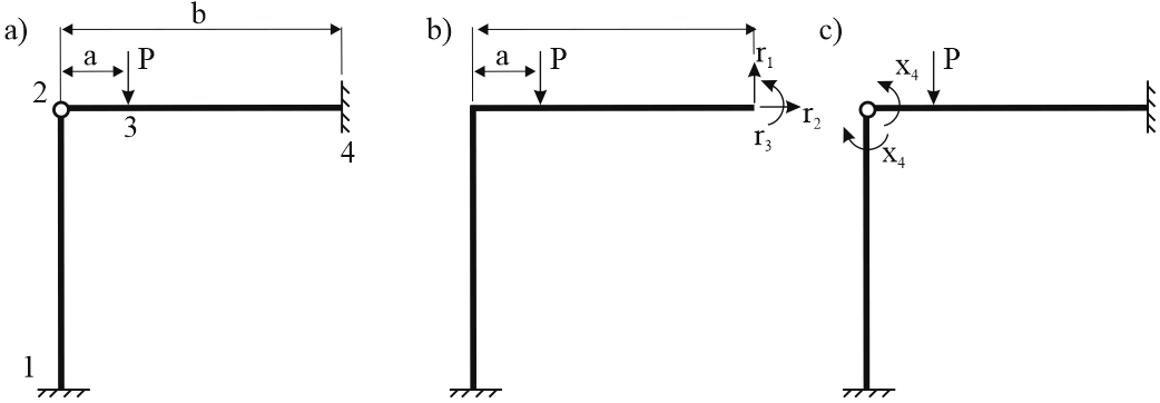
Example: 4-node frame (a) with anchors at nodes 1 and 4, hinge at node 2, and force at node 3

a - frame model, b - flexibility method primary structure, c - stiffness method primary structure
Flexibility method primary system (b): remove anchor 4 and apply unknown loads r1, r2, r3. Creates cantilever system from anchor 1. Node 2 is rigid.
Stiffness method primary system (c): hinge at node c with unknown displacement x4.
System equations:

Bottom equation states hinge moment equals zero:

This method was selected during PASS/START-PROF development in 1965 for minimal memory usage and fastest solution of tree-like piping systems. On modern hardware, it quickly solves complex nonlinear systems.
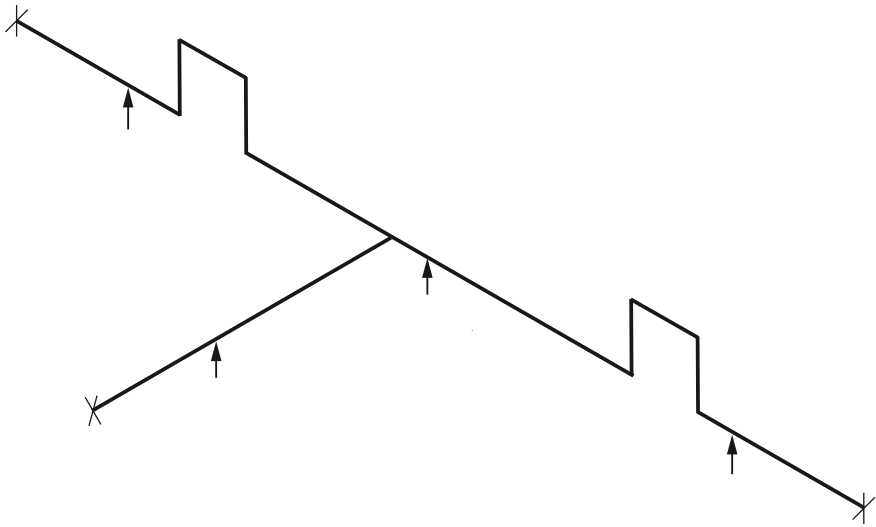
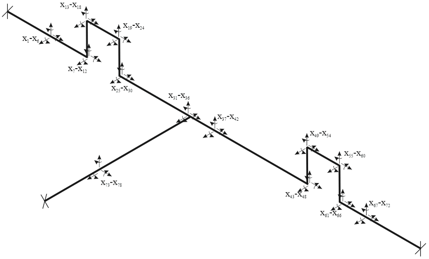
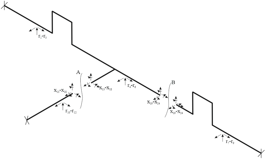
Example system:

Classical FEM stiffness method: 78 unknowns. K matrix is 78x78. High memory and computation time.

PASS/START-PROF combined method: 24 unknowns. 24x24 matrix with identical results.
Automatic cut-points A and B divide system into 3 cantilever sections.

Classical stiffness method: boundary conditions are zero displacements x at support nodes. With solution tolerance, support displacements remain zero.
Flexibility method: solution yields unknown forces r with tolerance. PASS/START-PROF then calculates displacements for all nodes in each cantilever using reaction forces r. Displacements also have tolerance, which may cause small non-zero displacements (e.g., 0.5 mm) at rigid supports. This is normal for very long cantilevers and requires no user action.
To improve displacement accuracy, add marker (M) objects. These break long cantilevers into shorter sections, adding 6 unknown reaction forces at each marker.

1. Magalif V., Yakobson L. Pipe stress analysis on computers (PASS/START-PROF authors). Moscow, 1969
2. Aynbinder A., Kamershtein A. Transmission pipelines stress and stability analysis. Moscow, 1982
3. Skomorovsky Y., Aynbinder A. Longitudinal displacements of buried pipelines considering soil physical nonlinearity, VNIIST, Moscow, 1975
4. Variable spring hanger selection for power and nuclear piping RTM 24.038.12-72, 1973
5. Weaver W., Gere J. Matrix Analysis of Framed Structures
6. Nagarajan P. Matrix methods of structural analysis