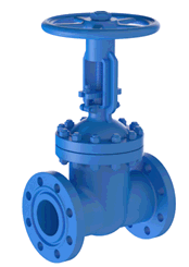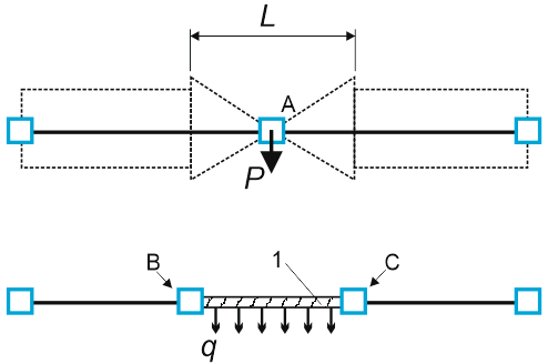

Valves are modeled as rigid elements with length L and weight P (Figure 1b). When you insert a valve at node A, PASS/START-PROF automatically creates two hidden nodes (B and C) and replaces the pipe section with a rigid element carrying uniform weight q=P/L.
The software removes the pipe weight for the section occupied by the valve. Fluid weight matches the connected pipes. Insulation weight is calculated at 1.75 times the connected pipe value. Distributed loads (fluid, insulation, snow, ice, wind, and user-defined) are applied proportionally—left half from the left pipe, right half from the right pipe. Thermal expansion of the rigid element is included in the analysis.
Perform flange leakage analysis for connected flanges.

1 - rigid element
Figure 1. Valve model

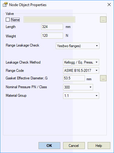
| Property | Description |
Name |
Element identifier. When checked, displays in 3D view |
Length |
Valve length. Includes counter-flange length (distance between pipe ends) |
Weight |
Valve weight including counter-flanges. Excludes insulation and fluid weight. Use nominal weight without load safety factors |
Flange leakage check |
Enable flange leakage analysis. Configure parameters in flange properties |
To insert a valve:
1. Select the target node
2. Use Insert
> Insert Valve or click 
To view valve properties:
Double-click the valve in the 3D view
Select the valve and click 