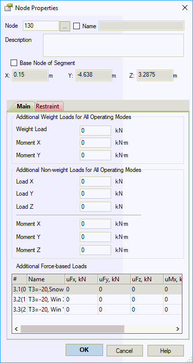
A node defines any point along the pipe centerline used for data input. Nodes always occur at:
Pipe branches or direction changes
Support, valve, or expansion joint locations
Pipe cross-section changes
Concentrated load application points
Temperature change points
Node types include:
End nodes
Intermediate nodes
Branch nodes
Nodes are numbered from 1 to 31,999. Numbering sequence is arbitrary.

| Property | Description |
Name |
Node identifier. Displays in 3D view, output tables, and reports when enabled. To show node names in 3D view, click |
Base node of segment |
Defines coordinate origin for independent piping segments within one file. Each segment requires one base node with fixed global coordinates. Base nodes remain fixed during pipe dimension changes. Assign via right-click menu. |
Analyze segment |
Excludes segment from analysis when unchecked |
X, Y, Z |
Global coordinates relative to origin (0,0,0). Used for independent piping segments |
Description |
User comments and notes |
Elevation from Ground |
Height above ground level for wind and ice load calculations. Editable for base nodes only |
Additional weight loads |
Concentrated weight loads. Manually apply overload factors per applicable standards . Applies to all operating modes. Includes in mass calculation for seismic analysis |
Additional non-weight loads |
Concentrated non-weight loads in global coordinates. Manually apply overload factors per applicable standards . Applies to all operating modes. Excludes from mass calculation for seismic analysis |
Apply concentrated forces and moments to nodes. Follow START-PROF sign convention for direction input.
Example: For a horizontal-axis steering wheel, input moment and vertical force.

Double-click any node in 3D view to open node properties.