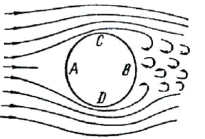

Wind loads are applied to all above-ground pipe elements and fittings in the global coordinate system. The load magnitude depends on the angle between the element axis and wind direction:

 - uniform wind load components in global coordinate system
p - uniform wind load calculated per selected design code
ω - angle between element Xm vector and wind direction vector. Load is zero when wind flows parallel to pipe axis. Maximum load occurs when wind is perpendicular to pipe.
X,Y,Z - wind vector direction cosines
To exclude wind loads on specific elements, set wind shape factor to zero.
When wind and ice loads are combined, the insulation diameter Dk (D) increases by ice layer thickness.
Supported wind load design codes:
ASCE 7-22 (USA)


D – Insulation outer diameter (specified in pipe properties)
Cf – Wind shape factor (specified in pipe properties). If "Auto" option is on:

G=0.85
Kd=1
Kz – Velocity pressure exposure coefficient from table, depend on exposure (B,C,D)

KBC 2016 (Korea)

D – Insulation outer diameter (specified in pipe properties)
GD=0.85
CD – Wind shape factor (specified in pipe properties). If "Auto" option is on:

EN 1991-1-4:2005+A1:2010 (European Union)


D – Insulation outer diameter (specified in pipe properties)
Cp – Wind shape factor (specified in pipe properties)
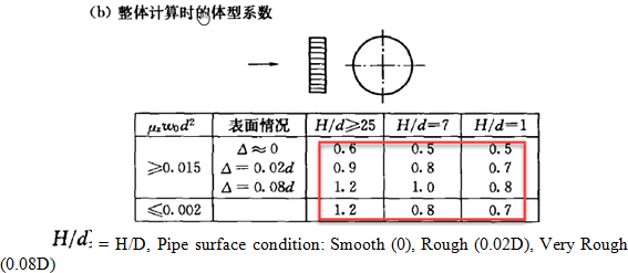
GB 50009-2012 (China)

D – Insulation outer diameter (specified in pipe properties)
 – Wind shape factor (specified
in pipe properties). If "Auto" option
is on:

IS.875.3.2015 (India)


D – Insulation outer diameter (specified in pipe properties)
Cf – Wind shape factor (specified in pipe properties). If "Auto" option is on:

SP 20.13330.2016 (Russia)


Dk – Insulation outer diameter (specified in pipe properties)
c - Wind shape factor (specified in pipe properties)
IBC 2021 (International): Same as for ASCE 7-22
NSR-10 (Colombia): Same as for ASCE 7-22
UBC 1997

D – Insulation outer diameter (specified in pipe properties)
Cq – Wind shape factor (specified in pipe properties)
AZ/NZS 1170.2:2021 (New Zeland)

D – Insulation outer diameter (specified in pipe properties)
Cfig - Wind shape factor (specified in pipe properties)
NBC 2020 (Canada)


D – Insulation outer diameter (specified in pipe properties)
Cp – Wind shape factor (specified in pipe properties)
NBR 06123-1988 (Brazil)

D – Insulation outer diameter (specified in pipe properties)
Ca – Wind shape factor (specified in pipe properties)
BS 6399-2 (Britain)


D – Insulation outer diameter (specified in pipe properties)
Cp – Wind shape factor (specified in pipe properties)
TKP EN 1991-1-4 2009 (Belarus): Same as for EN 1991-1-4:2005+A1:2010
CNS (Taiwan)

D – Insulation outer diameter (specified in pipe properties)
Cf – Wind shape factor (specified in pipe properties)
CFE 2020 (Mexico)


D – Insulation outer diameter (specified in pipe properties)
Ca – Wind shape factor (specified in pipe properties)
Kre - correction factor (specified in pipe properties)
Dubai Wind Code


D – Insulation outer diameter (specified in pipe properties)
Ca – Wind shape factor (specified in pipe properties)
Wind Pressure vs Elevation

D – Insulation outer diameter (specified in pipe properties)
c - Wind shape factor (specified in pipe properties)
Wind Velocity vs Elevation

c – Wind shape factor (specified in pipe properties)
D – Insulation outer diameter (specified in pipe properties)
Blast Load (DNV RP D101)


Cf – Drag coefficient (specified in pipe properties)
D – Insulation outer diameter (specified in pipe properties)
Property |
Description |
Insulation Outer Diameter |
Insulation outer diameter is used for calculation of upwind surface area. If wind and ice loads added simultaneously then diameter of insulation is increased by the ice layer thickness automatically |
Elevation of Start/End Node |
Greatest elevation from ground surface is used for calculation of wind load. By default, the elevation above the ground surface for wind and ice load calculation is calculated automatically assuming that the ground plane is horizontal. The option "Recalculation of elevation above a ground surface" should be switched off for pipelines laying on the ground surface with variable heights |
Wind Direction |
Select wind direction in global coordinate system. If "other" option is selected, then angles between wind direction vector and global axes X, Y, Z should be entered. Number of wind directions is unlimited |
First Frequency, f1 |
First natural frequency of the piping system. Can be obtained from normal modes analysis |
Basic Wind Speed |
V, section 26.5
Fundamental Value of Basic wind speed Vb,0
Vb
V
V
V
V
Vo
Vo
Vb
Same as for EN 1991-1-4:2005+A1:2010
VR
V |
Basic Wind Pressure |
w0
q
pN |
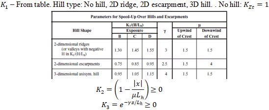
Hill Type |
|
Average slope, |
|
Height of Hill, H |
|
Crest Distance, Lh |
|
Distance from Crest to Site, x |
|
Importance factor, Iw |
|
Wind Exposure Terrain Category |
Open Terrain, Rough Terrain
|
Pipe Surface Condition |
Smooth (0), Rough (0.02d), Very Rough (0.08d)
Smooth, Rough
Smooth (0), Rough (0.02D), Very Rough (0.08D) |
Total Wind Height, H |
Ho - upwind building height
Zt |
Risk Factor, k1 |
|
Topography Factor |
|
Cardinal Direction Hill Shape Multiplier, Mh Lee Effect Multiplier, Mlee Surface Roughness Height, hr Shielding Multiplier, Ms |
Cardinal direction: N, NE, E, SE, S, SW, W, NW, Any Direction
|
Site Elevation (Altitude) |
Site elevation above mean sea level, in metres
hm |
Surface Roughness, hr |
hr, 0.003 mm - 15 mm
hr, 0.003 mm - 15 mm |
Temperature |
t - ambient air temperature |
Statistical factor, S3 Roughness category Dimension class |
|
Directional Factor |
The value of the directional factor, Cdir, for various wind directions may be found in the National Annex. The recommended value is 1,0 |
Seasonal Factor |
The value of the season factor, Cseason, may be given in the National Annex. The recommended value is 1.0 |
Building-type factor, Kb Probability factor, Sp Upwind Building Spacing, Xo Upwind Building Height, Ho Pipe Location Closest Distance to Sea Upwind Size Effect Factor, Ca |
Pipe Location:
Size Effect Factor Ca
|
Structural Factor CsCd Turbulence Factor KI |
Turbulence Factor KI The value of turbulence factor may be given in the National Annex. The recommended value is 1.0 |
Importance factor for cyclonic region, k4 |
|
dynamic load factor, DLF |
Default value 2.0 |
Density of combustion gases |
Default 1.226 kg/m3 |
Snubbers |
Define the snubbers are active or not active for wind loads |
Dialog window opens automatically when creating a new analysis file or opening an existing analysis file. To open this window in an open file, use File > Project Settings