
Tabs:

To insert a pipe, select the start node and insert pipe element. End node creates automatically if not specified. To insert between existing nodes, select both nodes or specify node numbers manually.
Property |
Description |
Name |
Element identifier for sorting and selection in project tree |
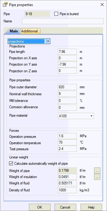
Projections\sphere\cylinder1 |
Five input methods for element dimensions:
|
External diameter, D |
Pipe outside diameter |
Pipe length |
Pipe element length
|
Real length |
Actual pipe length including bends
|
Manufacturing technology |
For ASME B31.1, ASME B31.3, DL/T 5366-2014: seamless pipe uses Wl=1.0. Electric-welded pipe Wl from database. More... For GOST 32388-2013, pipe properties from different materials databases based on pipe type (seamless/welded). |
Material |
Material selection from materials database |
Nominal wall thickness, S |
Nominal (actual) wall thickness |
Mill tolerance |
Manufacturing tolerance. More... |
Liner thickness, tL |
Liner thickness for FRP piping. Used to calculate reinforced wall thickness tr=t-tL-tc and mean diameter Dr=D-2*tc-tr
|
Topcoat thickness, tc |
External protective layer thickness for FRP piping |
Corrosion/Erosion allowance |
Wall thickness allowance for corrosion and erosion. More... |
Pressure, P |
Design pressure for all standards except SNIP 2.05.06-85 and SP 36.13330.2012. Operating pressure for SNIP 2.05.06-85 and SP 36.13330.2012. Varies
by operating mode. Click |
Temperature, Тop |
Design temperature in operating mode. More... Varies
by operating mode. Click |
Thermal Gradient |
Temperature difference between pipe top and bottom ΔT=Ttop-Tbottom. Models thermal bowing effect on horizontal pipes. More... Click
|
Installation pressure, Passembly |
Pressure in installation state. See wall thickness analysis |
Automatic pipe weight calculation |
Pipe weight calculated as
Material density from materials database |
Uniform pipe weight |
Uniform pipe and attached structure weight. More... |
Uniform insulation weight |
Uniform insulation weight. More... Varies
by operating mode. Click |
Insulation Thickness, ti Insulation Density Cladding Thickness, tc Cladding Density Lining Thickness, tl Lining Density |
1 - pipe, 2 - insulation, 3 - cladding, 4 - lining, t - pipe wall thickness, ti - insulation thickness, tc - cladding thickness, tl - lining thickness
|
Uniform product weight / product density |
Uniform product weight or product density. More... Varies
by operating mode. Click |

Property |
Description |
Longitudinal Weld Joint Efficiency Factor, E |
Longitudinal weld joint efficiency factor. More... |
Coefficient y |
B31.3 temperature and material dependent coefficient
|
Design Factor, F |
For ASME B31.8 Onshore:
For ASME B31.12PL:
|
Design Factor, a |
For BS PD 8010 Onshore:
|
Location Factor, L |
For CSA Z662: Table 4.2
|
Basic Design Factor, FA, FB |
For CSA Z662: Table 11.1
|
Steel Performance Factor, Mf Steel Performance Factor, Hf |
ASME B31.12:
|
High Pressure |
Apply ASME B31.3 Chapter IX requirements for high pressure piping |
Pipeline Location |
Offshore Pipeline: Apply ASME B31.4 Chapter IX or ASME B31.8 Chapter VIII requirements Slurry Pipes: Apply ASME B31.4 Chapter XI requirements |
Pipeline Type |
Restrained Pipeline - Apply restrained pipe code requirements. See details. Unrestrained Pipeline - Apply unrestrained pipe code requirements. See details. Riser or Platform for Inland Waterways or Platform Piping - Apply riser code requirements For automatic detection, select Autodetect or START Smart Check in Project Settings. See details. |
Creep diminish factor2, |
Compensation stress averaging factor
for high-temperature pipelines
per RD 10-249-98 section 5.2.3.6, GOST
32388-2013 section 7.1.7. Set
to 0 for low-temperature pipelines. Click |
Creep self-springing factor2,
|
Compensation stress relaxation factor
for high-temperature pipelines
per RD 10-249-98 section 5.2.3.7, GOST
32388-2013 section 7.1.7. Set
to 0 for low-temperature pipelines. Click |
Pipeline category |
Pipeline category per SNIP 2.05.06-85 table 1: B, I, II, III, IV. Determines operating condition factor m |
Product |
Product type: gas, oil, oil products. Used for safety factor calculation per SNIP 2.05.06-85 |
Safety factor K1 |
Material safety factor K1 per SNIP 2.05.06-85 table 9 |
Safety factor K2 |
Material safety factor K2 per SNIP 2.05.06-85 table 10 |
Safety factor based on load n for internal pressure |
Load safety factor n for internal pressure per SNIP 2.05.06-85 table 13 |
Safety factor, Ky |
Plastic piping (HDPE) safety factor. Obtain from manufacturer. See Thermoplastic Piping Stress Analysis
|
Chemical resistance factor, A2 |
FRP/GRP/GRE piping chemical resistance factor. Use 1.0 for non-aggressive products |
Chemical resistance factor, Kx |
Plastic piping (HDPE) chemical resistance factor. Use 1.0 for non-aggressive products. Obtain from manufacturer. See Thermoplastic Piping Stress Analysis |
Laying condition factor, Kp |
Plastic piping installation factor
|
Temperature range factor, k |
Plastic and fiberglass piping temperature range factor. Accounts for nonlinear temperature distribution across wall thickness. Recommended: 1.0 for thermoplastic, 0.85 for fiberglass (fluid), 0.8 for fiberglass (gas). See Thermoplastic Piping Stress Analysis |
Swelling strain, e3 |
Plastic piping swelling strain. Obtain from manufacturer. See Thermoplastic Piping Stress Analysis |
Strength factor of joint, Кс |
Plastic piping joint strength factor. Obtain from manufacturer. See Thermoplastic Piping Stress Analysis
|
Design Factor, Df |
Design factor per ASME NM.1 table 2-3.2.2-2 |
Design Factor, DFt |
Test mode design factor. Default: DFt=1 |
Type |
Laminate type |
Safety Factor γm |
EN 13941 safety factor:
|
Project Class |
EN 13941 project class (A, B, C). Select Auto for automatic determination based on:
rg - average pipe radius |
Pipeline Type |
EN 13941 pipeline type determines equivalent full action cycles.
Specify cycle values in Project Settings:
|
Additional weight load |
Additional uniform weight load applied in all operating modes. Manually apply overload factors per applicable standards. Included in mass calculation for dynamic (seismic) analysis |
Additional non-weight load |
Additional uniform non-weight load applied in all operating modes. Input global coordinate axis projections. Manually apply overload factors per applicable standards. Excluded from mass calculation for dynamic (seismic) analysis |
Note 2: Low- and high-temperature pipelines distinguished by creep diminish and self-springing factor values. Zero values indicate low-temperature piping. Non-zero values indicate high-temperature piping, regardless of actual temperature and steel grade.
For mixed piping (low- and high-temperature elements), set temperature differences accordingly. Overall analysis treats as high-temperature piping.
Click  for automatic factor calculation. For materials
in RD 10-249-98 or GOST 32388-2013, calculation is instant. Otherwise,
select equivalent steel with corresponding factors.
See Loads and effects combination, high- and low-temperature pipelines, pressure thrust force.

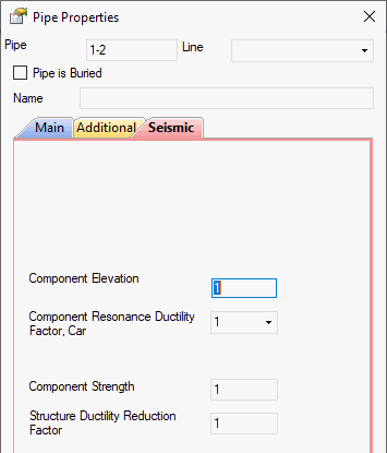
Component elevation |
ASCE 7-22, KBC 2016, EN 1998-1: z/h
NSR-10, NBC 2020: hx/hn UBC 1997: hx/hr |
Component resonance ductility factor, Car |
|
Component strength factor |
|
Structure ductility reduction factor |
|
|
|
Piping placement |
Piping placement selection
|
Function factor Ko |
SP 14.13330.2018 table 3, SNIP II-7-81* table 16, SP 36.13330.2012 table 15 |
Factors Kh, Kv |
Height and structure type dependent increasing factors |
Structure type |
Factors Kh, Kv depend on supporting structure stiffness and mass
|
Soil deformation module above 10000 MPa |
Apply 1.5 increasing factor for soil deformation module above 10000 MPa |
Peak ground velocity, Vg |
Reference table for peak ground acceleration conversion (ASCE 2001):
|
Peak ground acceleration, Ag |
Apply 1.5 increasing factor for soil deformation module above 10000 MPa |
Apparent P-Wave Propagation Velocity, Cp Apparent S-Wave Propagation Velocity, Cs |
Default: Cp=2 km/s, Cs=2 km/s. Reference table for wave velocity values:
Data from "Методические рекомендации по определению динамических свойств грунтов, скальных пород и местных строительных материалов. П01-72. // ВНИИГ им. Б.Е. Веденеева, 1972" Calculate wave speed based on soil layers thickness and individual layer wave speeds:
|
Property |
Description |
| Insulation Outer Diameter | Insulation outer diameter. Default: pipe outer diameter if zero specified |
| Start Node Elevation from Ground | Ground surface elevation for wind and ice load calculation |
| End Node Elevation from Ground | Ground surface elevation for wind and ice load calculation |
| Snow Shape Factor | Zero value disables snow load
|
| Thermal Coefficient |
|
| Snow (and Rain) Load | Normative snow load value. Automatically multiplied by safety factor per code |
| Ice Shape Factor | Zero value disables ice load
|
| Ice Load | Normative ice load value. Automatically multiplied by safety factor per code |
| Wind Shape Factor | Zero value disables wind load
|
| Correction factor |
|
| Wind Direction Number / Wind Load | Normative wind load value for each direction and global axis projections. Automatically multiplied by safety factor per code |
START-PROF performs wall thickness check for all pipe elements per selected code.
To insert a pipe, select the desired node and use: Insert > Insert Pipe
or click  toolbar icon.
To view element properties:
Double-click element in 3D view
Select element
and click  toolbar icon