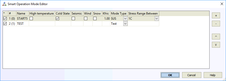
The Operation Mode Editor enables analysis of multiple piping operating conditions within a single project file. This high-level tool automatically generates specialized load case templates for operating modes and user-specified force-based load combinations. Manual load case creation is eliminated, allowing engineers to focus on piping design rather than load case configuration. The editor ensures proper load case combinations without human error or knowledge gaps.
You can add either Operation Modes or Force Loads.
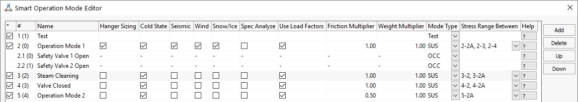
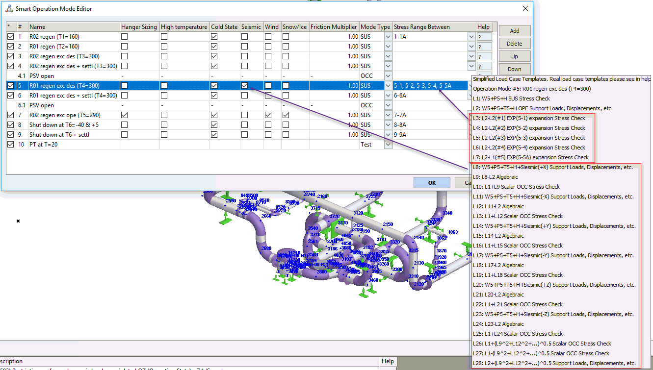
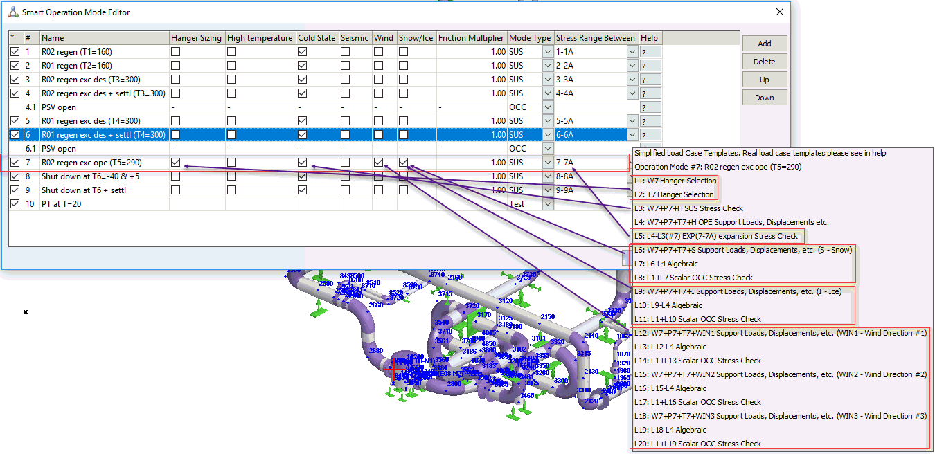
Operation Mode - Defines a specific piping operating condition with pressure, temperature, fluid weight, support displacements, and other parameters (labeled 1, 2, 3, etc.). Main operation modes model displacement-based loads such as normal operation, emergency scenarios, testing, steaming, or ship piping hog/sag conditions. Each main operation mode includes hot and cold states.
Force Loads - Additional forces applied to specific operating modes (labeled 4.1, 6.1, etc.). These model sustained and occasional loads including safety valve thrust, slug flow, water hammer, blast, wind, snow, and ice loads. Apply concentrated forces at nodes and uniform forces along pipes. The number of force loads is unlimited.
The example below shows five operation modes: Main, steaming, filling, discharging, and test. Operation mode 2 includes two additional force loads (relief valve 1 and 2).
Click the "?" help buttons to view online descriptions of automatically generated load case templates:
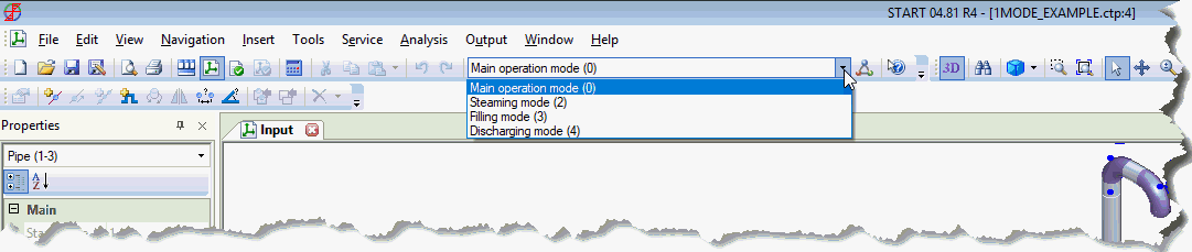
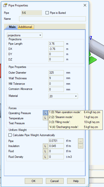
Close this window after adding all operation modes. Use the toolbar to select the current operation mode. All data display and entry applies only to the current operation mode. Pipe properties show pressure and temperature for the current operating mode only. To view another mode's properties, change the current operation mode and reopen pipe properties.
Properties that vary by main operating mode:
Pressure
Temperature
Fluid density
Insulation weight
Additional uniform pipe loads
Additional nodal loads
Support movements
Ambient temperature in Project settings
All other properties remain constant across operating modes.
When multiple operating modes are specified, the first sustained operating mode determines La and Lb calculations for all modes.
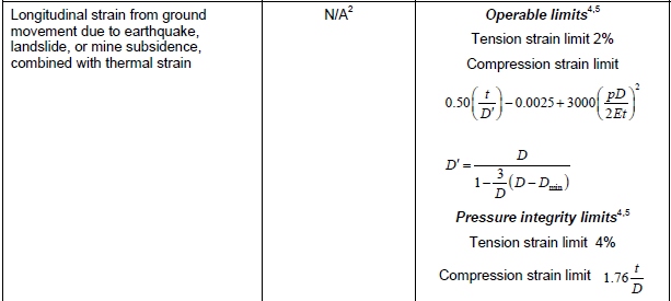
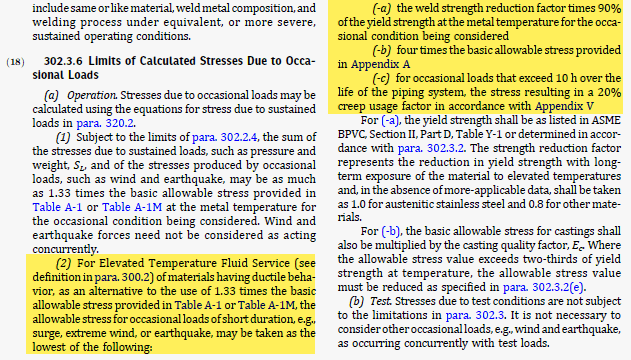
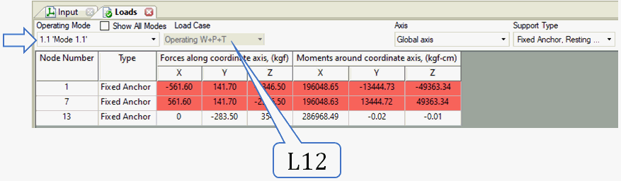
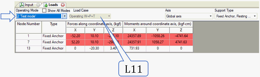
Multiple operation modes trigger "L" buttons next to mode-specific fields. Click these buttons to view property values across different operation modes.
New projects require at least one operating mode. If test mode analysis is enabled in project settings, include test mode as well. The example below shows the minimum operating mode set for a new project. Remove the first row if test mode is not required.
Property |
Description |
* |
Enable/disable operation mode. Uncheck to exclude from analysis. Recheck to reactivate. |
# |
Operation mode numbering. Main modes use integers (1, 2, etc.). Force-based loads use decimal notation (2.1, 2.2, 4.3, etc.) where the first number indicates the parent main mode. |
Name |
Descriptive operation mode name. Accepts any text input. |
Hanger Sizing |
Spring hanger selection occurs in one main operation mode only. START-PROF applies selected springs to all other modes. Selecting multiple modes is prohibited. No selection disables hanger sizing. |
High temperature |
Check for piping classified as high temperature per GOST 32388-2013. Requires entry of creep diminish and creep self-springing factors for high-temperature elements. |
Cold state |
Calculates a special "Cold State" mode with negative temperature equal to the installation/operation temperature difference. Friction force analysis starts from the Hot state (Operating Mode). For example, heating from -20°C to +50°C reaches the main operation mode, then cooling to -20°C achieves the cold state. Friction forces reverse direction during cooling. Cold state loads and stresses differ from installation conditions. Limit to one cold state per project. Multiple cold states are not meaningful. |
Seismic |
Generates additional load cases with multi-directional seismic inertial forces for the operating mode. Applicable to multiple modes. For example, seismic analysis at both 50°C and 200°C operation. |
Wind |
Generates additional load cases with multi-directional wind loads for the operating mode. Applicable to multiple modes, similar to seismic loading. |
Snow |
Generates additional load cases with snow and ice loads for the operating mode. Applicable to multiple modes, similar to seismic loading. |
Dynamic |
Performs dynamic analysis for this operating mode. |
Mode Type |
Operation mode categories:
|
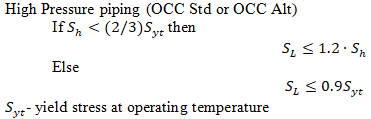
OCC(k) OCC Std OCC Alt |
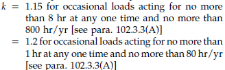
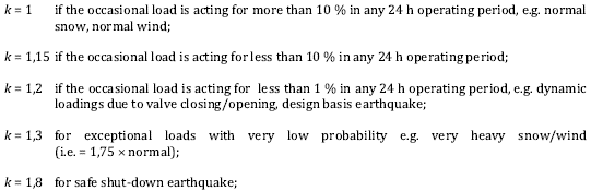
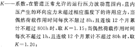
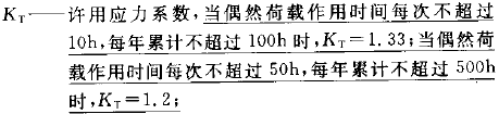
k-factor for occasional load allowable stress calculation per selected code. ASME B31.1, ASME B31.9:
ASME B31.5: k=1.33
GB/T 20801-2006: k=1.33
|
Time Duration, h |
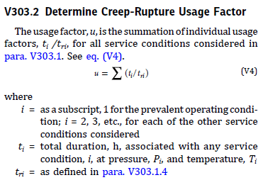
Operating mode duration. Used for ASME B31.3 Appendix V alternative occasional stress and creep-rupture usage factor (u) calculations.
|
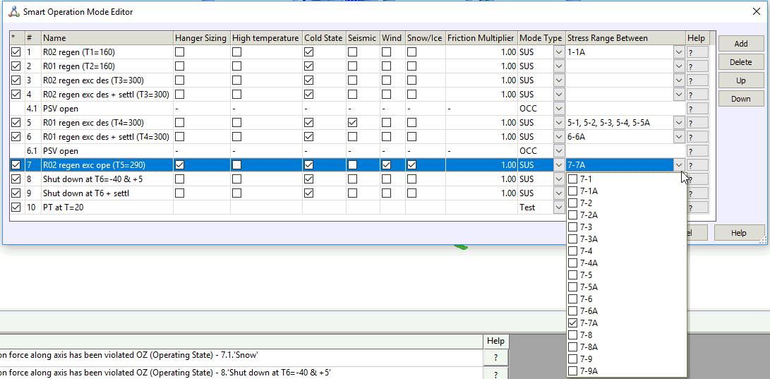
Stress range between |
Specify main operation modes for expansion stress range calculation. Limited to main operation modes only. |
Use Load Factors |
Disables code-required overload factors (EN 13941, GOST 32388, SP 36.13330, etc.). Enables more accurate spring selection. Note: Analysis with full overload factors may result in spring loads exceeding allowable limits. |
Friction Multiplier |
Friction factor coefficient (0...1.0). Use 0 for frictionless analysis, 0.5 for half friction, and 1.0 for full model friction. Friction typically diminishes during piping vibration. Recommended multipliers: 0 or 0.5 for wind, seismic, water hammer, slug flow, relief valve thrust, and other dynamic loads. Not applied to slip joint and torsion expansion joint. |
Friction Multiplier <cold> |
Additional friction factor coefficient (0...1.0) for cold state (cooling stage). Used in EN 13941 and CJJ/T 81-2013 codes. AGFW FW 401 recommends 0.5 for cold state. This multiplier applies in addition to the main friction multiplier. All friction factors are multiplied by both the main multiplier and this cold state multiplier during cooling analysis. |
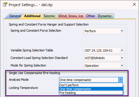
Spec. Analyze |
Enables special analysis types like single-use compensator cold spring or pre-heating for the current operating mode. Select analysis type in Project Settings.
|
Weight Multiplier |
Zero weight multiplier used during nozzle load reduction and piping flexibility analysis. Zero weight ensures nozzle loads result from thermal expansion only. Values greater than 1 used for transportation stage analysis or sea bed settling. |
Snubbers Active |
Locks snubbers for this force-based load case, restricting displacements from additional forces. |
START-PROF automatically generates template load cases based on operation mode editor specifications after analysis execution.
START-PROF piping analysis uses a differential friction model. Sequential state transitions follow the chain: "installation mode" - "operating mode" - "cold mode". Each state analyzes the deformed condition. Cold mode analysis starts from the operating mode stressed-deformed state, then applies weight plus negative temperature difference (cooling). Friction forces at each support first reverse direction while the support remains stationary, then begin moving toward installation positions. Supports do not return to original installation positions.
Theoretically, multiple "operation state" - "cold mode" cycles could be analyzed. Experimental data shows the first heating-cooling cycle produces the highest stress amplitude, making it sufficient for fatigue failure margin determination.
High-pressure pipelines with creep experience elastic deformation transitioning to plastic (residual) deformation. This gradually reduces operating mode stress and creates negative cold mode stress. RD 10-249-98 section 5.2 and GOST 32388-2013 use averaging factor χ and relaxation factor δ for creep pipeline safety analysis, decreasing real temperature difference in operating mode and increasing it in cold mode. This approximate safety analysis provides margin but doesn't accurately calculate node displacement (determining piping deformed shape, visible displacement, and support loads). START-PROF performs separate analyses to address this limitation:
Operating mode stress relaxation ignored for equipment support load calculations (first heating analysis without χ and δ factors).
Post-relaxation piping state used for safety analysis and equipment load analysis in cold state (including averaging factor χ and relaxation factor δ).
L - Load case
T - Design temperature
Tambient - Ambient temperature, input in Project Settings
Tt - Test temperature, input in Project Settings
P - Design pressure
Pt - Test pressure
Sh - Allowable stress at hot temperature
Sc - Allowable stress at cold temperature
Sy - Yield stress at test temperature
St - Allowable stress at test temperature
fat - Fatigue curve
SUS - Sustained
OPE - Operational
OCC - Occasional
HGR - Hanger selection
CLD - Cold
EXP - Expansion
F - Additional non-weight loads. Considered in all operating modes. Excluded from seismic load calculations.
Fw - Additional weight loads. Considered in all operating modes. Included in seismic load calculations (Fw+W).
H - Variable or constant spring hanger force
CS - Cold spring
W - Pipe weight + Insulation weight + Fluid weight (composition varies by code). Insulation weight may be zero in installation state. GOST 32388, GOST 55596 and similar codes use: pipe weight*1.1 + Insulation weight*1.2 + fluid weight*1.0 or alternative combinations per code requirements.
Ww - Pipe weight + Insulation weight + (water or zero weight at test state)
D - Support displacement at operation state
Dt - Support displacement at test state
Dd - Support settlement
E, alfa - Elastic modulus and thermal expansion factor
χ - Creep stress averaging factor
δ - Creep stress relaxation factor
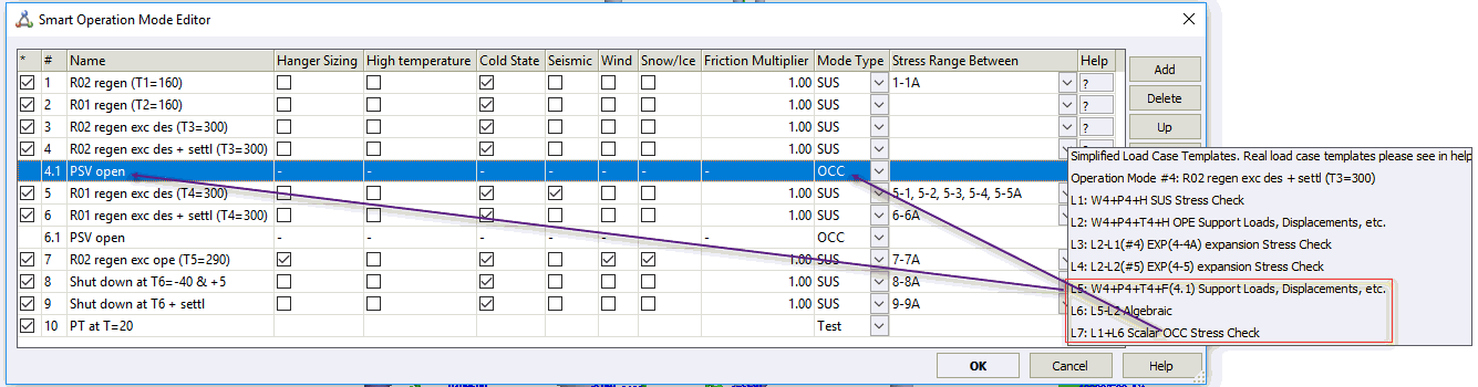
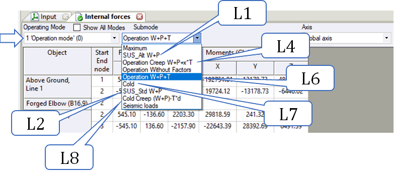
Template loads cases are shown in table below:
Load cases LH1 - LH2 are performed for operation modes in which the "Spring Selection" option is activated
Load cases L1 - L6 are performed for each main operation mode
Load case L7 is performed for operation modes in which the "Cold State" option is activated
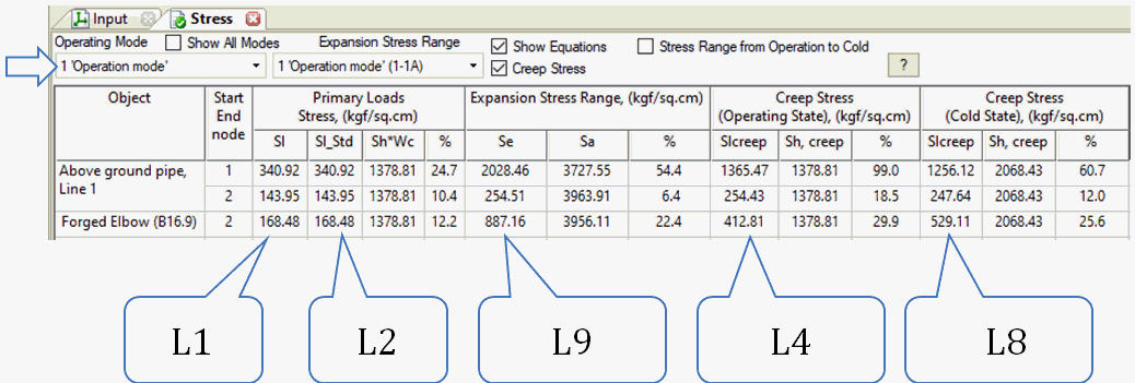
L9 check is performed between cold and hot mode and between different operation modes
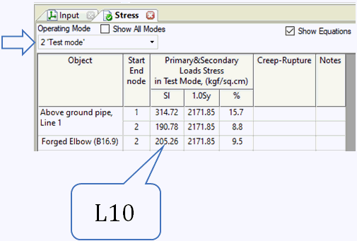
Load case L10 is performed for test mode
Load cases L11 - L13 are performed for each additional force-based loading
Load cases L4 and L8 are performed for main operation mode in which the "Creep" option is activated
If options "Seismic", "Wind", "Snow" are selected then automatically performed several additional load case analysis for seismic, wind and snow loads
Option 1. Consider hot modulus for support loads (in Project Settings)
Option 2. Stress range from operation to cold (in Project Settings and Stress Table)
Note: SIF and k-facrtors are calculates using maximum pressure from all load cases except occasional and test, and used for all load cases except occasional.
See also piping operating modes for more information.
# |
Name |
Load case |
Allowable stress |
one way link, gap |
Spring Stifness |
E |
Alfa |
Bend k-factor |
Output |
LH1 |
Hanger selection |
W1+F+Fw |
- |
Calc |
Single-directional rigid |
Tambient
or T1 |
- |
P1 |
|
LH2 |
T1+D1+Dd |
- |
Calc |
Stiffness iteration |
Tambient
or T1 |
T1 |
P1 |
||
L1 |
Weight in operation State 1 |
W1+P1+F+Fw+H |
SL<k*W*Sh |
L5 |
Designed |
Tambient |
- |
P1 |
|
L2 |
Installation state 1 |
W1+P1+F+Fw+H+CS+Dd1 |
- |
Calc |
Designed |
Tambient |
- |
P1 |
|
L4* |
Operation with creep 1 |
W1+P1+F+Fw+H+χ·T1+χ·D1+Dd1 |
SL<1.0*Sh |
Calc |
Designed |
Tambient |
T1 |
P1 |
|
L5 |
Operation for loads 1 |
W1+P1+F+Fw+H+T1+CS+D1+Dd1 |
- |
Calc |
Designed |
Tambient
or T1 |
T1 |
P1 |
|
L6 |
Operation for expansion 1 |
W1+P1+F+Fw+H+T1+CS+D1+Dd1 |
- |
Calc |
Designed |
Tambient |
T1 |
P1 |
- |
L7 |
Cold after cooling down 1 |
L6-T1-D1 |
- |
Calc |
Designed |
Tambient |
T1 |
P1 |
|
L8* |
Cold after relaxation (creep) 1 |
W1+P1+F+Fw+H-δ·T1-δ·D1 |
SL<1.5*Sc |
Calc |
Designed |
Tambient |
T1 |
P1 |
|
L9 |
Expansion |
L6-L7 or L6-L2 (option 2) |
Se<Sa |
- |
Designed |
- |
- |
P1 |
|
L10 |
Test state |
Ww+Pt+F+Fw+H |
SL<0.9*Sy |
Calc |
Single-directional rigid / Designed |
Tambient |
Tt |
Pt |
|
L11 |
Ww+Pt+F+Fw+H+Tt+CS+Dt+Dd |
- |
Calc |
Single-directional rigid / Designed |
Tambient |
Tt |
Pt |
||
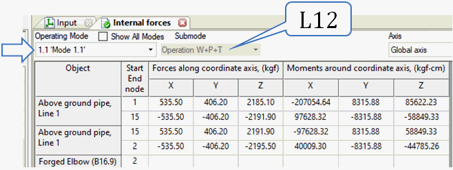
L12 |
Additional Force loading 1.1 |
W1+P1+F+Fw+H+T1+CS+D1+Dd1+F1.1 |
- |
Calc |
Single-directional rigid / Designed |
Tambient |
T1 |
P1 |
|
L13 |
L12-L6 |
- |
- |
- |
- |
- |
- |
- |
|
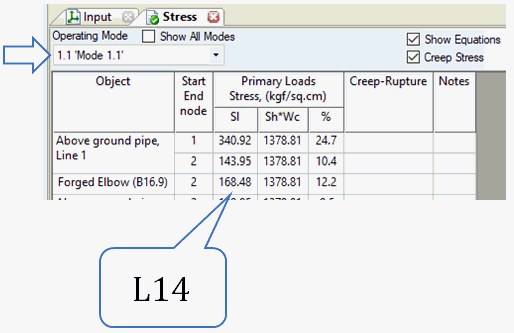
L14 |
L1+L13 |
SL<k*W*Sh |
- |
- |
- |
- |
- |
* - additional non-code load cases to consider the creep effect (detailed creep analysis requirements are missing in B31.1 and B31.3 codes)
On the screenshot below the explanation where are the each load case is used.
Stresses:
Loads, Displacements, Expansion Joint Deformation
Internal Forces
Non-creep piping uses the template load cases below:
L1 - L2: Operation modes with activated "Spring Selection"
L3 - L5, L4*: Each main operation mode with mode type = SUS (sustained)
L6 - L8: Operation modes with activated "Cold State"
L9: Check between cold/hot modes and different operation modes
L10: Test mode
L11 - L12: Each main operation mode with mode type = OCC (occasional)
L13 - L15: Each additional force-based loading
"Seismic", "Wind", "Snow" options generate additional load cases for seismic, wind, and snow loads
# |
Name |
Load case |
Allowable stress |
One way link |
Spring |
E, alfa |
Bend k-factor |
Output |
L1 |
Hanger selection |
W1+F+Fw |
- |
Calc |
Single-directional rigid |
T1 or Tambient |
P1 |
|
L2 |
T1+D1+Dd |
- |
Calc |
H |
T1 |
P1 |
||
L3 |
SUS W+P1 |
W1+P1+F+Fw |
Sc |
Calc |
H |
T1 |
P1 |
|
L4 |
EXP W+P1+T1+D1+Dd - W+P1 |
T1+D1+Dd |
fat |
Calc |
H |
T1 |
P1 |
|
L5 |
OPE W+P1+T1+D1+Dd |
W1+P1+F+Fw+T1+D1+Dd |
- |
Calc |
H |
T1 |
P1 |
|
L4* |
EXP W+P1+T1+D1+Dd - W+P1 |
T1+D1+Dd |
fat |
Calc |
H |
T1 |
P1 |
|
L6 |
CLD W+P1+T1+D1+Dd |
W1+P1+F+Fw+T1+D1+Dd |
- |
Calc |
H |
Tambient |
P1 |
|
L7 |
EXP W+P1+T1+D1+Dd - W+P1+T1+D1+Dd |
Tambient |
fat |
Calc |
H |
Tambient |
P1 |
|
L8 |
OPE W+P1+T1+D1+Dd |
W1+P1+F+Fw+T1+D1+Dd |
- |
Calc |
H |
Tambient |
P1 |
|
L9 |
EXP W+P1+T1+D1+Dd - W+P1+T1+D1+Dd |
Tambient |
fat |
Calc |
H |
Tambient |
P1 |
|
L10 |
TEST Wt+Pt |
Wt+Pt+F+Fw |
St |
Calc |
H |
Tt |
Pt |
|
L11 |
OCC W+P1+OCC |
W1+P1+F+Fw+OCC |
k*Sh |
Calc |
H |
T1 |
P1 |
|
L12 |
OCC W+P1+T1+D1+Dd+OCC |
W1+P1+F+Fw+T1+D1+Dd+OCC |
k*Sh |
Calc |
H |
T1 |
P1 |
|
L13 |
OCC W+P1+4.1 |
W1+P1+F+Fw+4.1 |
k*Sh |
Calc |
H |
T1 |
P1 |
|
L14 |
OCC W+P1+T1+D1+Dd+4.1 |
W1+P1+F+Fw+T1+D1+Dd+4.1 |
k*Sh |
Calc |
H |
T1 |
P1 |
|
L15 |
EXP W+P1+T1+D1+Dd+4.1 - W+P1+4.1 |
T1+D1+Dd |
fat |
Calc |
H |
T1 |
P1 |
High-temperature piping (creep) uses the template load cases below:
L1 - L2: Operation modes with activated "Spring Selection"
L3 - L5, L4*: Each main operation mode with mode type = SUS (sustained)
L6 - L8: Operation modes with activated "Cold State"
L9: Check between cold/hot modes and different operation modes
L10: Test mode
L11 - L12: Each main operation mode with mode type = OCC (occasional)
L13 - L15: Each additional force-based loading
"Seismic", "Wind", "Snow" options generate additional load cases for seismic, wind, and snow loads
# |
Name |
Load case |
Allowable stress |
One way link |
Spring |
E, alfa |
Bend k-factor |
Output |
L1 |
Hanger selection |
W1+F+Fw |
- |
Calc |
Single-directional rigid |
T1 or Tambient |
P1 |
|
L2 |
χ*T1+D1+Dd |
- |
Calc |
H |
T1 |
P1 |
||
L3 |
SUS W+P1 |
W1+P1+F+Fw |
Sc |
Calc |
H |
T1 |
P1 |
|
L4 |
EXP W+P1+χ*T1+D1+Dd - W+P1 |
χ*T1+D1+Dd |
fat |
Calc |
H |
T1 |
P1 |
|
L5 |
OPE W+P1+χ*T1+D1+Dd |
W1+P1+F+Fw+χ*T1+D1+Dd |
- |
Calc |
H |
T1 |
P1 |
|
L4* |
EXP W+P1+χ*T1+D1+Dd - W+P1 |
χ*T1+D1+Dd |
fat |
Calc |
H |
T1 |
P1 |
|
L6 |
CLD W+P1+δ*T1+D1+Dd |
W1+P1+F+Fw+δ*T1+D1+Dd |
- |
Calc |
H |
Tambient |
P1 |
|
L7 |
EXP W+P1+δ*T1+D1+Dd - W+P1+χ*T1+D1+Dd |
δ*T1 |
fat |
Calc |
H |
Tambient |
P1 |
|
L8 |
OPE W+P1+δ*T1+D1+Dd |
W1+P1+F+Fw+δ*T1+D1+Dd |
- |
Calc |
H |
Tambient |
P1 |
|
L9 |
EXP W+P1+δ*T1+D1+Dd - W+P1+χ*T1+D1+Dd |
δ*T1 |
fat |
Calc |
H |
Tambient |
P1 |
|
L10 |
TEST Wt+Pt |
Wt+Pt+F+Fw |
St |
Calc |
H |
Tt |
Pt |
|
L11 |
OCC W+P1+OCC |
W1+P1+F+Fw+OCC |
k*Sh |
Calc |
H |
T1 |
P1 |
|
L12 |
OCC W+P1+χ*T1+D1+Dd+OCC |
W1+P1+F+Fw+χ*T1+D1+Dd+OCC |
k*Sh |
Calc |
H |
T1 |
P1 |
|
L13 |
OCC W+P1+4.1 |
W1+P1+F+Fw+4.1 |
k*Sh |
Calc |
H |
T1 |
P1 |
|
L14 |
OCC W+P1+χ*T1+D1+Dd+4.1 |
W1+P1+F+Fw+χ*T1+D1+Dd+4.1 |
k*Sh |
Calc |
H |
T1 |
P1 |
|
L15 |
EXP W+P1+χ*T1+D1+Dd+4.1 - W+P1+4.1 |
χ*T1+D1+Dd |
fat |
Calc |
H |
T1 |
P1 |
Load cases:
Load cases L1 - L2, L5 are performed for operation modes in which the "Spring Selection" option is activated
Load cases L3, L3*, L3** are performed for each main operation mode
Load case L4 is performed for test mode
Load case L6 is performed for each additional force-based loading
If options "Seismic", "Wind", "Snow" are selected then automatically performed several additional load case analysis for seismic, wind and snow loads
# |
Name |
Load case |
Allowable stress |
one way link |
Spring |
E, alfa |
Bend k-factor |
Output |
L1 |
Hanger selection |
W1+F+Fw |
- |
Calc |
Single-directional rigid |
T1 |
P1 |
|
L2 |
T1+D1+Dd |
- |
L1 |
Stiffness iteration |
T1 |
P1 |
||
L3 |
Operation Mode 1 |
W1+P1+T1+D1+F+Fw+S+Dd+H |
Calc |
Designed |
T1 |
P1 |
||
L3* |
W1+P1+T1+D1+F+Fw+S+Dd+H |
Calc |
Designed |
T1 |
P1 |
|||
L4 |
Test Mode |
Ww+Pt+Tt+Dt+Dd+S+H |
Calc |
Single-directional rigid / Designed |
Tt |
Pt |
||
L5 |
Cold Mode 1 |
L3-P1-T1-D1 |
- |
Calc |
Designed |
Tambient |
0 |
|
L6 |
Additional Force loading 1.1 |
W1+P1+T1+D1+F+Fw+S+Dd+H+F1.1 |
Calc |
Designed |
T1 |
P1 |
Note * - analysis uses standard load values without considered load safety factors
File > Operation Mode Editor