

PASS/START-PROF performs seismic analysis according to these design codes:
SNiP II-7-81* Building in Seismic Areas
SP 14.13330.2018 Construction in Seismic Regions
NP-031-01 Nuclear Power Plant Seismic Design
GB50011-2001 Code for Seismic Design of Buildings
User-Defined Acceleration
Seismic analysis considers responses from:
Pipe deformation from seismic wave propagation in soil (buried pipelines)
The software then calculates combined responses from all seismic and static load components.
PASS/START-PROF uses these methods for seismic inertial force analysis:
Equivalent static method (implemented in PASS/START-PROF)
Response spectrum analysis
Time history analysis
Equivalent static method calculates structural responses using equivalent static loads applied in different seismic directions. This method offers simplicity and accounts for structural nonlinearities like unilateral restraint engagement, which response spectrum analysis cannot handle. However, it doesn't consider higher vibration modes. To compensate, safety factors are applied, and seismic acceleration is set to maximum spectral values.
Response spectrum analysis provides more accurate results than the equivalent static method, typically yielding lower pipe responses due to frequency-dependent acceleration assessment. This method uses acceleration spectra to calculate modal seismic loads for each natural frequency. Modal responses are combined using specialized formulas to determine design values.
Time history analysis delivers the most accurate results, accounting for physical, geometric, and structural nonlinearities. This resource-intensive method is reserved for critical pipelines. It requires input acceleration records (accelerograms) and models pipe movement during seismic events, capturing maximum response values over time.
PASS/START-PROF implements the equivalent static method with conservative margins. Inertial forces are calculated as:

1.3 - static method correction factor accounting for inaccuracies versus response spectrum analysis (higher mode effects)
 - pipe element
mass (concentrated nodal or distributed)
 - (Alpha1 for GB50011-2001)
maximum spectral acceleration per selected design code (SNiP
II-7-81*, SP 14.13330.2018, NP-031-01, GB50011-2001)
 - vertical seismic
coefficient from PASS/START-PROF input data,
typically 0.65-0.75
For pipes on structures (buildings, ramps), seismic accelerations multiply by factor kh. Horizontal direction:

Vertical direction:

Determine factors according to applicable codes.
Eight load cases analyze inertial force responses:
L1: Operating static loads (W+P+T)
L2: Operating static loads (W+P)
L3: "+X" - operating loads + inertial forces (+X direction)
L4: "-X" - operating loads + inertial forces (-X direction)
L5: "+Y" - operating loads + inertial forces (+Y direction)
L6: "-Y" - operating loads + inertial forces (-Y direction)
L7: "+Z" - operating loads + inertial forces (+Z direction)
L8: "-Z" - operating loads + inertial forces (-Z direction)
Analysis accounts for structural nonlinearities (unidirectional restraints, gap supports), pendulum effects, and friction.
View results in output tables:

Maximum responses for each direction equal the difference between operating static loads (L1) and operating + inertial loads (L3-L8):
L9, L10:  maximum responses from "+X" and "-X"
(L3-L1, L4-L1)
L11, L12:  maximum responses from "+Y"
and "-Y" (L5-L1, L6-L1)
L13, L14:  maximum responses from "+Z"
and "-Z" (L7-L1, L8-L1)
Access results in output tables:
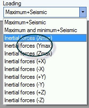
For SRSS(X,Y,Z) combination, displacements, support loads, and expansion joint deformations calculate as:
L12: L1 + (max(L9,L10)2 + Xmax_SAM2 + max(L11,L12)2 + Ymax_SAM2 + max(L13,L14)2 + Zmax_SAM2)0.5
L13: L1 - (max(L9,L10)2 + Xmax_SAM2 + max(L11,L12)2 + Ymax_SAM2 + max(L13,L14)2 + Zmax_SAM2)0.5
Xmax_SAM, Ymax_SAM, Zmax_SAM - seismic anchor movement responses (see below)
Stresses calculate as:
L12: L2 + (max(L9,L10)2 + Xmax_SAM2 + max(L11,L12)2 + Ymax_SAM2 + max(L13,L14)2 + Zmax_SAM2)0.5
SUS - sustained load case
Note: Stresses calculate separately for tensile and compressive zones, using the absolute maximum value.
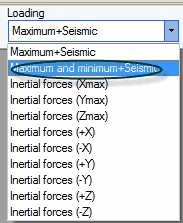
For MAX(X,Y,Z) combination, displacements, support loads, and expansion joint deformations calculate as:
L12: L1 + max(L9, L10, L11, L12, L13, L14, Xmax_SAM, Ymax_SAM, Zmax_SAM)
L13: L1 + min(L9, L10, L11, L12, L13, L14, Xmax_SAM, Ymax_SAM, Zmax_SAM)
Stresses calculate as:
L12: L2 + max(L9, L10, L11, L12, L13, L14, Xmax_SAM, Ymax_SAM, Zmax_SAM)
Maximum absolute responses calculate as:
L14: max(abs(L12), abs(L13))
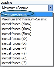
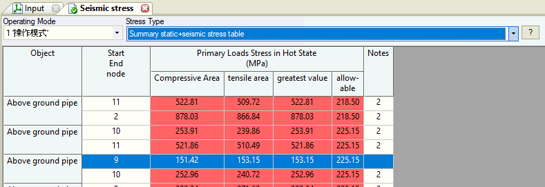
Seismic stress analysis checks two zones: compressive and tensile areas. This is critical for codes considering axial force and bending moment interactions.
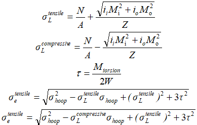

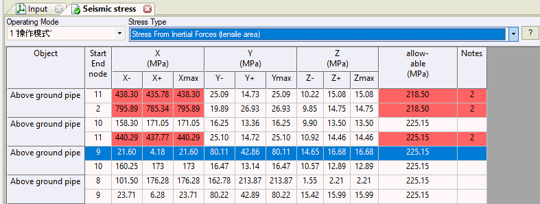
Tensile and compressive zone stresses calculate separately, with the highest value used for final assessment.
Piping systems often connect to multiple building attachment points or heavy equipment that move independently during seismic events. In addition to inertial forces, these relative displacements create significant static loads on the pipe.
To analyze these effects, specify seismic support displacement values and directions. Supports belong to "phase groups" - for example, all supports on one building floor belong to phase group 1, while supports on another floor belong to phase group 2. Each group moves independently, with unlimited groups permitted.
Obtain phase group displacement values from structural seismic analysis using specialized software.
Seismic anchor movements  represent maximum
possible X, Y, and Z displacements occurring at different times.
For each phase group, input three maximum displacement values along XYZ axes. Six load cases analyze each phase group:
L15: "+X" - operating loads + X displacement in +X direction
L16: "-X" - operating loads + X displacement in -X direction
L17: "+Y" - operating loads + Y displacement in +Y direction
L18: "-Y" - operating loads + Y displacement in -Y direction
L19: "+Z" - operating loads + Z displacement in +Z direction
L20: "-Z" - operating loads + Z displacement in -Z direction
Second phase group:
L21: "+X" - operating loads + X displacement in +X direction
L22: "-X" - operating loads + X displacement in -X direction
L23: "+Y" - operating loads + Y displacement in +Y direction
L24: "-Y" - operating loads + Y displacement in -Y direction
L25: "+Z" - operating loads + Z displacement in +Z direction
L26: "-Z" - operating loads + Z displacement in -Z direction
Analysis accounts for structural nonlinearities (unidirectional restraints, gap supports), pendulum effects, and friction.
Maximum responses for each direction equal the difference between operating static loads (L1) and operating + displacement loads:
Phase group 1:
L27: S_i_x = max(|L15-L1|, |L16-L1|)
L28: S_i_y = max(|L17-L1|, |L18-L1|)
L29: S_i_z = max(|L19-L1|, |L20-L1|)
Phase group 2:
L30: S_i_x = max(|L21-L1|, |L22-L1|)
L31: S_i_y = max(|L23-L1|, |L24-L1|)
L32: S_i_z = max(|L25-L1|, |L26-L1|)
Final responses calculate as SRSS combinations across all phase groups:
L33: Xmax_SAM = (L272 + L302 + ...)0.5
L34: Ymax_SAM = (L282 + L312 + ...)0.5
L35: Zmax_SAM = (L292 + L322 + ...)0.5