
How to Reduce the Nozzle Loads in
START-PROF
Read
about START-PROF pipe stress analysis software
When equipment loads exceed allowable values, first identify the cause.
High loads may result from:
- Force-controlled loads: Weight loads, pressure thrust forces.
Analyze with operating temperature equal to ambient temperature and
weight multiplier = 1.0
- Displacement-controlled loads: Thermal expansion, support
displacement. Analyze with weight multiplier = 0 in operation
mode editor
For high force-controlled loads:
- For weight loads: Add vertical supports, variable spring hangers,
or constant spring supports
- For expansion joint thrust forces: Redesign piping to remove non-pressure
balanced expansion joints or add anchors to resist thrust forces
For high thermal expansion loads, apply these methods:
- Increase piping system flexibility
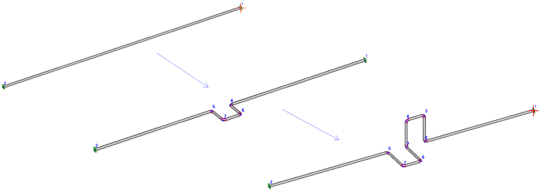
- Add bends - bends provide more flexibility
than straight pipe
- Reduce pipe and bend wall thickness where possible - thinner walls
increase flexibility
- Reduce diameter where possible - smaller diameters increase system
flexibility
- Add nozzle flexibility using WRC 297/PD
5500, API 650, or Nozzle
FEM
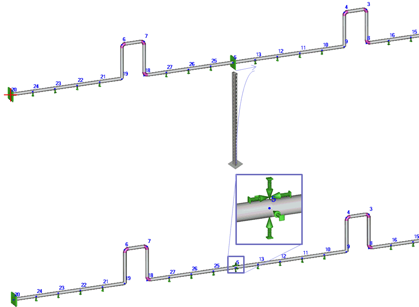
- Add support structure flexibility using custom
restraints with defined flexibilities
Example: Straight pipe between two anchors
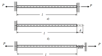
Without anchor flexibility, axial force calculates as:

With right nozzle flexibility λ:

Example: Pipe 219x6 mm, L=6m, ΔT=100°C, α=0.000012, E=2,000,000 kg/cm²,
A=40.1 cm²
 kgf
kgf
With nozzle flexibility λ=0.14 mm/tf (stiff nozzle), load reduces 3x:
 kgf
kgf
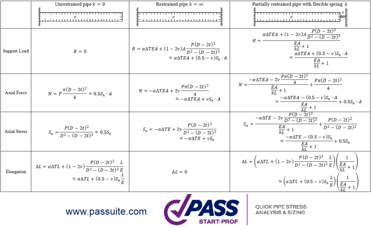
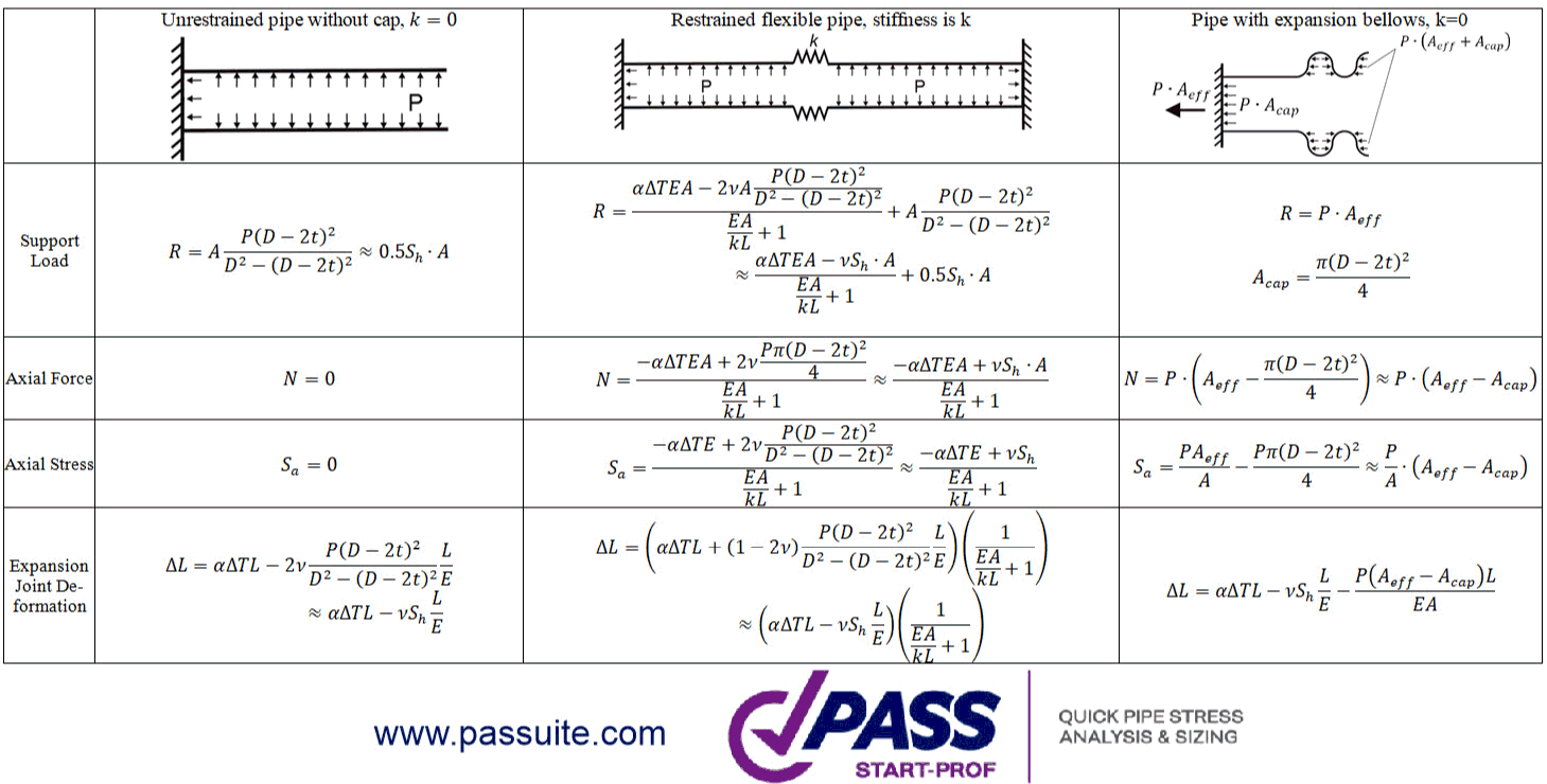
Complete equations for support loads, internal forces, and stresses:
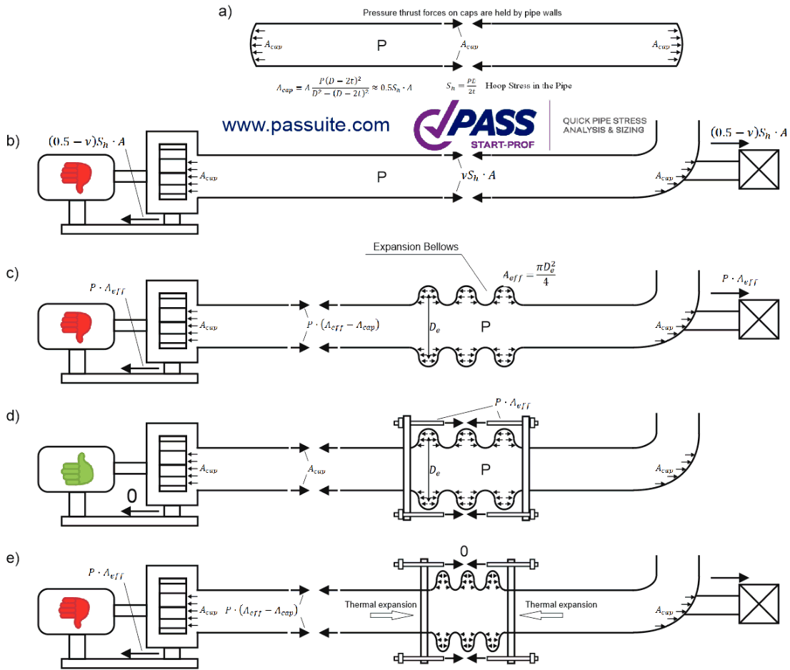
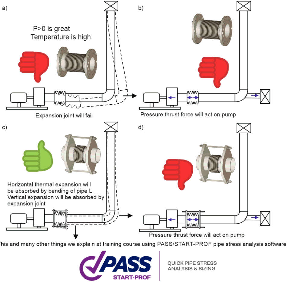
Use unbalanced expansion joints carefully - thrust forces may transfer
significant axial loads to equipment
Correct and incorrect pump piping with unbalanced expansion joints:
- Reduce temperature difference - lower operating temperature or
raise ambient temperature
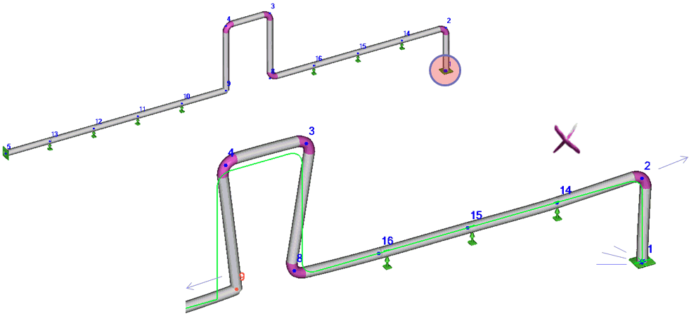
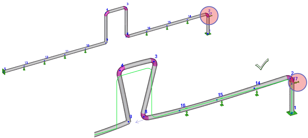
- Direct thermal expansion away from equipment using U-shaped loops
with proper restraints (guides or directional anchors). Consider friction forces in anchors
- For high friction loads: Use Teflon, graphite, or polished stainless
steel plates to reduce friction
- Use hot modulus of elasticity for equipment nozzle loads ("Use
Eh for support loads" in Project Settings)
- Apply cold spring as last resort (does
not reduce expansion stress range)
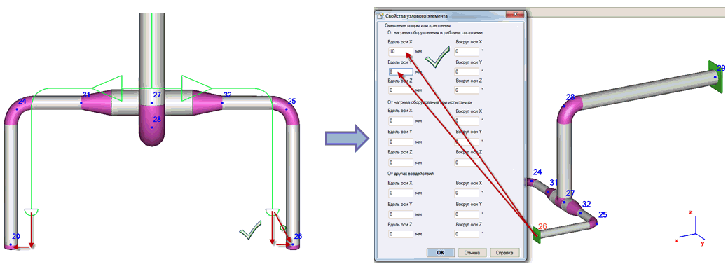
- Offset equipment by half the thermal expansion value from installation
to operating position
If loads remain above allowable limits after optimization, submit actual
loads (increased by 20% if piping data is not final) to equipment vendor
for FEA analysis and acceptance.


 kgf
kgf kgf
kgf


