Node deformation represents relative displacement between adjacent pipe cross-sections. Used for modeling expansion joint pre-stretch and other installation effects.
See also load combinations.
Apply node deformation to any straight pipe location except support/restraint positions. For support locations, create new node 1mm from support to input deformation effects.
Node deformation types:
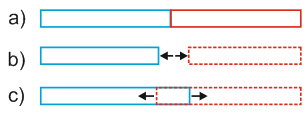
Pre-compression (Cold Push) (fig. 1.b). Special linear deformation case for pre-compression modeling.
Cold spring (Cut Short, Cold Pull) (fig. 1.c). Special linear end displacement case for pre-stretch modeling.
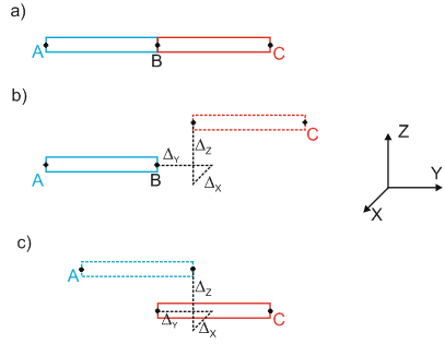
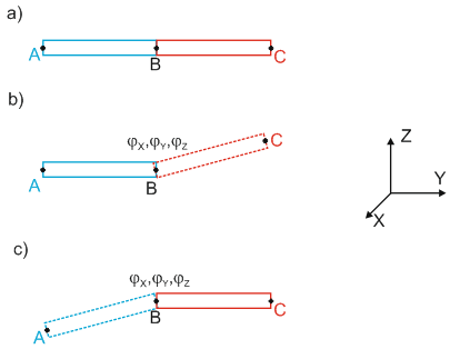
Linear and rotational node deformation. Relative pipe end displacement in any direction (fig. 2, 3)

a - initial condition, b - pipe compression, c - pipe tension
Fig. 1. Axial stretch and compression
Pre-stretch simulation: remove pipe section at node, force ends together, weld. Creates tension in adjacent elements. Pre-compression: insert additional pipe section at node, creating compression in adjacent elements.
Stretch/compression deformation applied along local element axis Xm.
Linear/rotational displacements input as projections on global coordinate axes, with positive/negative direction signs. Direction follows PASS/START-PROF global coordinate system.
Input relative displacement - one pipe end movement relative to another. Specify reference node for displacement.
Example: fig. 2.b shows element BC displacement relative to element AB. Reference node: A. Fig. 2.c shows element AB displacement relative to element BC. Reference node: C. Element containing reference node remains stationary; other element displaces by ΔX, ΔY, ΔZ. Fig. 2 shows identical ΔX, ΔY, ΔZ values produce different deformation patterns.

a - initial condition, b - linear displacement relative to node A, c - linear displacement relative to node C
Fig. 2. Relative pipe end linear displacement
Same principle applies to rotational displacement (fig. 3.b and c).

a - initial condition, b - angular displacement relative to node A, c - angular displacement relative to node C
Fig. 3. Relative pipe end rotational displacement
Insert > Displacement > Cold Spring (Cold Push)
Insert > Deformation > Cold Spring (Cold Pull)
Insert > Deformation > Move and Rotate Restraint
Insert > Deformation > Relative Displacement in Node