

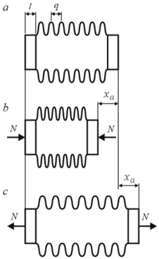
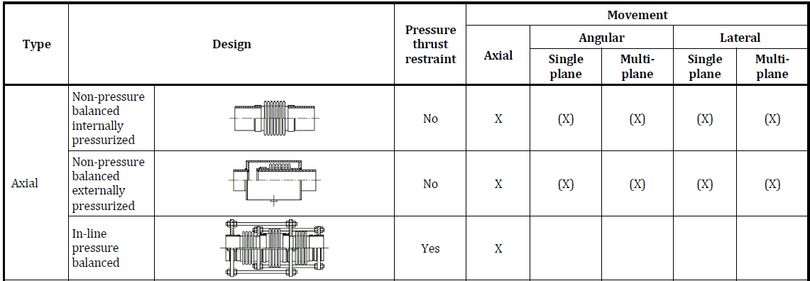
Axial expansion joints accommodate movement along pipe axis only.
Default configuration restricts bending and lateral movements.
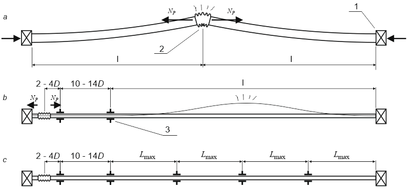
Install axial expansion joints on straight pipe sections between anchors.
Include appropriate guide supports as required.

Guide spacing determined by buckling stability analysis.
Enable "Allow bending and lateral movement" for non-straight pipe applications.
Software automatically calculates bending and lateral stiffness from axial stiffness.
Alternative: Use Universal Expansion Joint with manual stiffness input.
Bending stiffness (KR) and lateral stiffness (KL) calculated from axial stiffness (Kx):
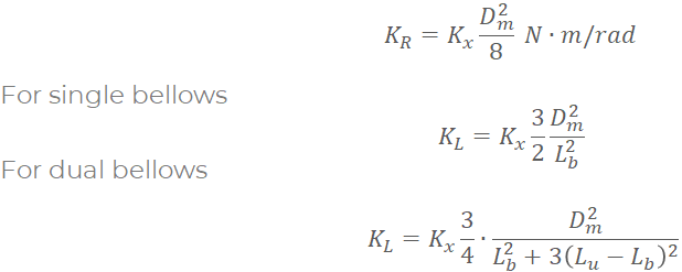
Where: Kx = axial stiffness, Dm = mean diameter, Lb = bellows length, Lu = total joint length
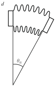
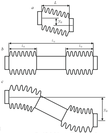
Equivalent axial deformation calculated in Expansion Joint Deformation Table:
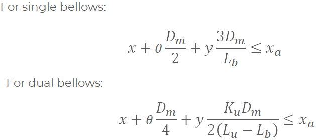
Lb – Bellows corrugated length
Lu – Distance between convolution ends
Dm – Bellows mean diameter
See also: Nozzle Load Reduction Techniques in START-PROF
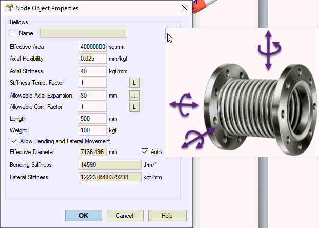
Access expansion joint properties from expansion joints database using "..." button.
Property |
Description |
Name |
Element identifier. Enable for 3D view display. |
Effective Area |
Pressure thrust calculation area. Bellows: Aeff = π × Dm² / 4 Dm ≈ (Dmin + Dmax)/2 (obtain from manufacturer) Pressure balanced joints: Aeff = 0 |
Axial Flexibility |
Total joint flexibility (1/Kx). Manufacturer data. |
Axial Stiffness |
Total joint stiffness (Kx). Manufacturer data. |
Stiffness Temp. Factor |
Elastic modulus correction for operating temperature. Ratio: E_operating / E_ambient Set per operation mode.
|
Allowable Axial Expansion |
Maximum axial movement: Δk/2 Δk = full allowable axial movement Used in deformation analysis. Manufacturer data. |
Allowable Correction Factor |
Movement adjustment for actual pressure and cycle count. Set per operation mode.
|
Length |
Expansion joint length Lu. Modeled as zero-length joint with flanking rigid elements. Use Flexible Element for non-zero length joints. |
Weight |
Joint weight distributed to flanking rigid elements. |
Allow Bending/Lateral Movement |
Enable bending and lateral stiffness calculation from axial stiffness. |
Effective Diameter |
Calculated from effective area.
|
Bending/Lateral Stiffness |
Automatically calculated from axial stiffness and geometry. |
Insert axial expansion joint at selected node: Insert > Expansion Joint > Axial Expansion Bellows