
START-PROF automatically accounts for pressure-related effects in piping systems:

Unrestrained pipe elongation from pressure consists of two components: elongation from end cap pressure load and shortening due to Hooke's Law.
Pipe elongation from end cap pressure load:

L – Pipe Length
E – Modulus of Elasticity
Pipe cross-section area:
D – Pipe Outer Diameter
t – Pipe Wall Thickness
N – Axial Force in the Pipe
Axial force equals the force acting on the end cap:

P – Internal Pressure
Pipe elongation:
Sh – Hoop Stress in the Pipe
According to Hooke's law, axial deformation under axial stress:
ν – Poisson’s Ratio
Pipe shortening due to internal pressure:
Total pipe elongation from pressure load:

Including thermal expansion elongation:

ΔT – Temperature difference between installation and operation
α – Coefficient of thermal expansion
Longitudinal stress from internal pressure:
Some codes use this strength criterion for unrestrained pipe:
Including bending stress M/Z and axial stress N/A from other loads:
For torsion stress, calculate equivalent stress:
Sallow - Allowable stress
Thermal expansion does not affect unrestrained piping systems. This equation typically checks sustained and occasional stresses from pressure, weight, and other force-based loads.
Code equations were designed for manual calculation. Modern pipe stress analysis software accounts for Bourdon effect, requiring code equation modifications.
START-PROF always calculates axial force N considering Bourdon effect. Subtract (PD/4t)A from axial force to avoid double-counting:
For restrained pipe with anchors at both ends, thermal and pressure expansion must be zero:

The axial force needed to compress the pipe to its original length:

Support load calculation:

Final support load for restrained pipe (Effective Axial Force):

Axial force from anchor equilibrium equals anchor reaction minus pressure thrust force:
Axial force in restrained pipe:
Axial stress in restrained pipe:
Strength criterion for fully restrained pipe:

Including bending stress M/Z and axial stress N/A from other loads:
For torsion and hoop stress, use equivalent stress equations as for unrestrained pipes.
When software calculates axial force N with Bourdon effect, subtract this value:
Replacing the rigid anchor with a flexible spring creates partially restrained conditions.
The table below shows final equations. "Support load" is also called "Effective axial force".
Strength criteria for partially restrained pipes from sustained primary loads:

From occasional primary loads:

From combined primary and secondary loads:
Primary loads: force-driven, non-self-limiting (weight, pressure, relief valve thrust, wind).
Secondary loads: displacement-driven, self-limiting (thermal expansion, anchor movements, support settlement).
Unrestrained and fully restrained conditions can be calculated manually. Partially restrained conditions require pipe stress analysis software due to spring stiffness dependency on connected pipes.
"Support Load, R" is called "Effective Axial Force". "Axial Force, N" is called "True Axial Force".
Use True Axial Force for:
Axial pipe stress calculation (Code Stress Table)
Local pipe wall buckling analysis (Pipe Wall Buckling Table)
Pipe element internal forces (Internal Forces in Piping Elements Table, with "Nozzle Loads" unchecked)
Use Effective Axial Force for:
Support load calculation (Loads on Supports and Restraints Table)
Pressure vessel and tank nozzle loads, rotating equipment loads (Loads on Nozzles and Equipment Table)
Flange leakage check (Flange Leakage Check Table)
Pipeline upheaval buckling (straight buried pipe, buried long-radius bend)
Pipeline global buckling (Euler buckling) (START-Elements)
Pipe element internal forces (Internal Forces Table, with "Nozzle Loads" checked)
Why use Effective Axial Force for nozzle loads, flange checks, and global buckling instead of True Axial Force?
When equipment manufacturers calculate allowable loads using FEM software like PASS/NOZZLE-FEM, they assume end caps and internal pressure. Axial stress from pressure thrust is already included in allowable loads.
Exclude pressure thrust load from True Axial Force for equipment nozzle checks. Use Effective Axial Force.
For a pipe with an end cap connected to a nozzle, True Axial Force equals PA, but Effective Axial Force is zero, resulting in zero nozzle load.
The same logic applies to flange leakage checks. Equivalent pressure method equations already account for internal pressure. Apply only additional loads from thermal expansion and other influences.
Why use Effective Axial Force for global and upheaval buckling, but True Axial Force for local pipe wall buckling?
Longitudinal buckling analysis considers the deflected pipe shape, not the initial installation shape. In a simple two-pipe model (a), "cap pressure" forces P·A create lateral force "S" that pushes the pipe sideways. Representing the pipe as a polygonal chain (b) shows lateral force "S" at each turn. With infinite polygons, uniform lateral load "S" causes global buckling.
Effective axial force "R" should be compared with critical axial force for buckling. For elastic buckling without soil resistance, Euler's equation applies:
Not true axial force "N". Additional "cap pressure" force generates distributed load "S". In deflected form, the outer pipe wall is longer than the inner wall, creating greater total pressure force on the outer surface by "S".
Another analogy: restrained pipe under pressure behaves like a reinforced concrete beam. The pipe acts as the reinforcing bar (tension), while the pipe content (water) buckles like a compressed rod.
PASS/START-PROF models Bourdon effect in any piping system. Pressure loads consist of two components.
First, START-PROF applies pressure thrust force to each pipe end:
Second, START-PROF adds axial deformation for each pipe: thermal elongation minus pressure shortening (Bourdon effect). Total axial expansion:

Combining these loads correctly models unrestrained, restrained, and partially restrained piping.
Bourdon effect significantly impacts support loads, displacements, and stresses for:
START-PROF always analyzes with Bourdon effect.
Internal pressure creates unbalanced forces on bellows end caps and convolutions (a), causing stretch in unrestrained pipelines (b). In restrained piping between supports, thrust force transfers to supports (c).
Fig. 3. Thrust force on supports in pipelines with axial expansion joints
Thrust force on supports in straight pipe ("cap pressure"):

Thrust force on supports in non-pressure balanced axial expansion joint:

Thrust force on supports in pressure balanced axial expansion joint: 0
START-PROF axial expansion joint model:
a - Thrust force in piping with axial expansion
joint
b - START-PROF model
c - Thrust force from expansion joint on anchors
Bourdon effect straightens initially ovalized bends under internal pressure, affecting displacements and support loads. Occurs only when ovalization factor a > 0.
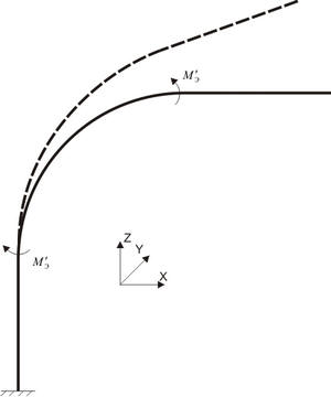
To model Bourdon effect, bending moments Me in the bend plane are automatically applied. Calculated using formulas from [1] and [2]:
Where:
a0 - Ovalization factor, %
Kp - Bend yield factor
Ke - Factor for cross-section ellipticity effect on bend axis skewing
R - Bend axis radius
1. Kostovetsky D.L. Pipe stress of power piping. St. Petersburg, 1973
2. Zverkov V.B., Kostovetsky D.L., Kats Sh.N., Boyaji K.I. Pipe stress analysis handbook. St. Petersburg, 1979