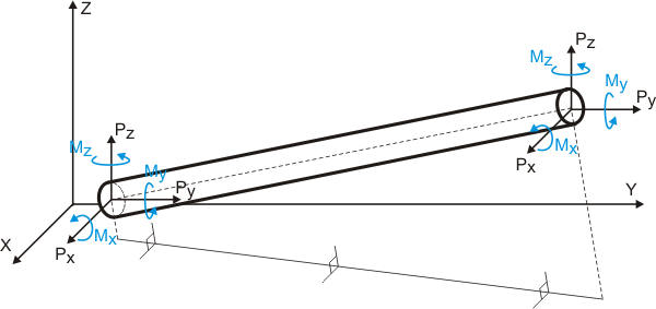
Forces acting in the direction of coordinate axes are positive. Moments following the right-hand rule (counter-clockwise when viewed from the positive axis direction) are positive.
Forces display in the following configurations (Fig. 2):
Straight pipe elements between nodes M and N (Fig. 2a). Forces display at pipe cross-sections 1 and 2 adjacent to nodes M and N, viewed from the opposite node.
Valve at node N of element M-N (Fig. 2b). Forces display at cross-sections 1 and 2. Section 1 adjoins node M from node N side. Section 2 adjoins the valve from node M side.
Bend at node N of element M-N (Fig. 2c). Forces display at cross-sections 1 and 2. Section 1 adjoins node M from node N side. Section 2 adjoins the bend from node M side.
For tees, forces in run pipes display at sections 1 and 2 of node N (Fig. 2d). Forces in branch pipes display at section 3 of a dummy node located at half the run diameter from node N.
A - Automatically added nodes (invisible), B - Dummy node (visible in 3D view)
Fig. 2
Two force lines display for each element. Forces do not display for bends since they equal forces in adjacent pipe sections.
The FORCES table lists elements in the order they appear in the input data.
Table view and content depend on these properties:
Property |
Description |
Operating Mode |
Select the operating mode for results display.
Maximum - Displays the maximum value from all operating modes in each cell. View analysis results for force-based loads, seismic, wind, and ice loading. |
Submode |
PASS/START-PROF calculates several submodes (piping states) for each operating mode.
For details, see load combinations. |
Occasional Loads |
|
Show Effective Axial Force |
For nozzle or valve load calculations, subtract thrust force P×Ac from axial load, where P is internal pressure and Ac = π×(D-2t)²/4 is the cap area (D = outer diameter, t = wall thickness). Learn more about effective axial force. |
Coordinate System |
Forces and moments display in these coordinate systems:
Fig. 1. Internal forces in pipe element |
The detailed internal forces table supports copying to Excel for stress calculations per standards not implemented in PASS/START-PROF.
Faxis(+thrust) - Axial force including pressure thrust
Faxis(-thrust) - Axial force excluding pressure thrust
Shear - Resultant shear force (√(Fy² + Fz²))
Torsion - Torsional moment
Bending - Resultant bending moment (√(My² + Mz²))
P - Pressure
D - Diameter
s - Wall thickness
C1 - Manufacturing thinning allowance
C2 - Corrosion allowance
mat - Material
Ea, Et - Modulus of elasticity at installation and operating temperature
S - Allowable stress at operating temperature
Sy - Yield strength
St - Ultimate tensile strength
Fibw - Weld strength reduction factor for bending
Fiw - Weld strength reduction factor for tension
R - Bend radius
Flange - Number of flanges in bend: 0, 1, 2
Padt, PadL - Reinforcement pad thickness and width for tee
rx - Tee crotch radius
Alfa - Reducer cone angle
io, ii, it, ia - Stress Intensification Factors (SIFs)
After analysis: Output > Internal Forces & Moments