

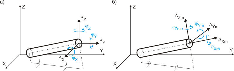
This table displays linear and rotational expansion joint deformation as projections on coordinate axes. Linear deformation represents mutual pipe end displacement, while rotational deformation shows mutual rotation of pipe ends. Deformation sign depends on local axes direction of adjoining elements.
For universal expansion joints, relative displacements are checked using:
Add torsion rotation term if allowable torsion values are available.
For axial expansion joints, equivalent axial deformation ratio calculates as:
Lb – Corrugated bellows length
Lu – Distance between convolution ends
Dm – Mean bellows convolution diameter
For single-use compensators, deformation values display for welding moment conditions (at welding temperature specified in Project Settings).
Table view and content depend on these properties:
Property |
Description |
Operating Mode |
Select operation mode for result display
"Maximum" displays maximum values from all operation modes View results from additional force-based loadings including seismic, wind, and ice loading |
Design state selection |
Software calculates multiple submodes (piping states) for each operating mode:
See force and effect combination for details. |
Occasional Loads |
|
Axis |
Linear and rotational deformation displayed as projections on coordinate axes:
Fig. 1. Expansion joint deformation in global and local coordinate systems |
| Note | Description |
Expansion joint skew exceeds allowed |
Expansion joint skew conditions not met |
Deformation exceeds axial expansion |
Condition |
Deformation exceeds rotational expansion |
Actual rotational deformation exceeds allowable rotational expansion. Modify piping model or expansion joint properties. |
Deformation exceeds lateral expansion |
Actual lateral deformation exceeds allowable lateral expansion. Modify piping model or expansion joint properties. |
After analysis: Output > Expansion Joint Deformations
 .
.
 not met. Actual equivalent axial deformation exceeds allowable