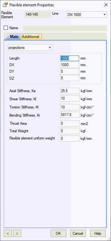


The flexible element is a two-node component for modeling expansion bellows and flexible hoses. Unlike single-node expansion joints (zero-length), this element has finite length with beam properties. Specify bending stiffness four times greater than for zero-length expansion joints.

Property |
Description |
Name |
Element identifier. Sort and select elements by name in the project tree |
Coordinate Input Method1 |
Projections:
Input dimensions as projections on global
coordinate axes DX, DY, DZ |
Stiffness
Properties |
Shear stiffness (Kl) and bending stiffness (Kr) are automatically calculated using: Kl = Kr × 3/L² and Kr = Kl × L²/3 Where: Kr = Bending Stiffness (N·m/rad) Kl = Shear Stiffness (N/m) L = Bellows length (m) Important: Two-node flexible elements require bending stiffness four times greater than zero-length expansion joints. Comparison of flexible element types:
For identical applied moment M, rotation angle θ₂ = 4 × θ₁, requiring KR(two-node) = 4 × KR(zero-length)
Multiply manufacturer's bending stiffness values by 4 for two-node flexible elements |
Thrust Area |
Models pressure thrust forces in flexible piping. Set to zero for pressure-balanced expansion joints |
Total Weight |
Total element weight |
Uniform Weight |
Distributed weight along element length |
To insert a flexible element:
Select the desired node
Use menu: Insert > Flexible Element
To view element properties:
Double-click the element in the 3D view
Select the element and click the  toolbar
icon