

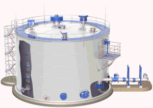
Learn more about PASS/START-PROF pipe stress analysis software
Tank connections require special modeling considerations compared to pressure vessels. PASS/START-PROF automatically accounts for:
Analysis results appear in the Nozzle and Equipment Loads Table. See also Nozzle Load Reduction Methods in PASS/START-PROF
Tank nozzle objects at pipe ends automatically model settlement and thermal expansion. For intermediate nozzles, model these effects manually using rigid elements and cylindrical shells.
Tank object at end node:
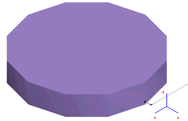
Tank object at intermediate node. Model thermal expansion with rigid elements and settlement with anchor movement:
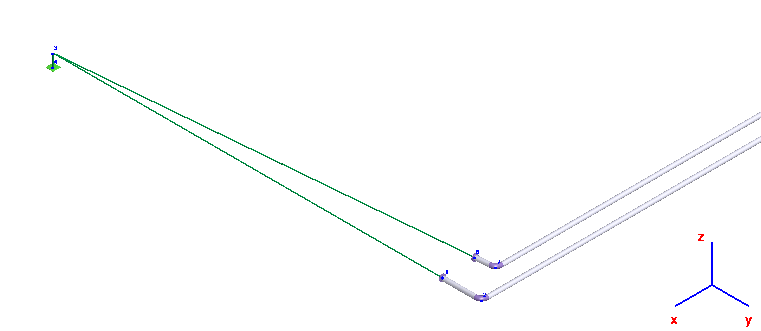
Vertical rigid element replaced by cylindrical shell:
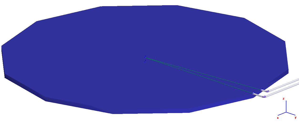
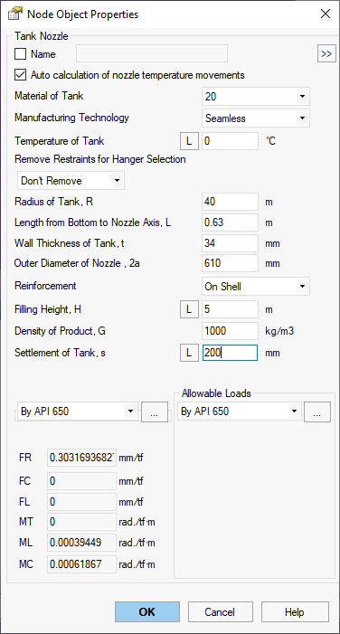
Property |
Description |
Name |
Element identifier. Sort and select elements in project tree |
Material of Tank |
Material from materials database |
Manufacturing technology of Tank |
For ASME B31.1, ASME B31.3, DL/T 5366-2014, seamless pipe uses Wl=1.0. Electric-welded pipe uses database Wl values. More... For GOST 32388-2013, material properties vary by pipe type (seamless/welded). |
Temperature of Tank |
Design temperature in operating condition. More... This
property varies by operating condition.
View values across conditions using |
Remove restraints for hanger selection |
When enabled, removes specified restraints during spring hanger selection weight analysis. Restraints remain active during main analysis. This technique isolates weight loading from nozzle elements.
|
Radius of Tank, R Length from bottom to nozzle axis, L Wall thickness of tank, t Outer diameter of nozzle, 2a Reinforcement On Neck, On Shell |
|
Filling Height, H |
Height from bottom to liquid surface. This property varies
by operating condition. View
values across conditions using |
Density of Product, G |
Liquid density |
Settlement of Tank, s |
Tank settlement value. This
property varies by operating condition.
View values across conditions using |
Nozzle flexibility |
Flexibility options:
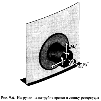
FR - Axial flexibility along nozzle axis FC - Transverse flexibility perpendicular to nozzle and vessel axes FL - Transverse flexibility perpendicular to nozzle axis, parallel to vessel axis MT - Torsional flexibility around nozzle axis ML - Angular flexibility in nozzle-vessel plane MC - Angular flexibility out of nozzle-vessel plane
|
Allowable loads |
Allowable load options:
|
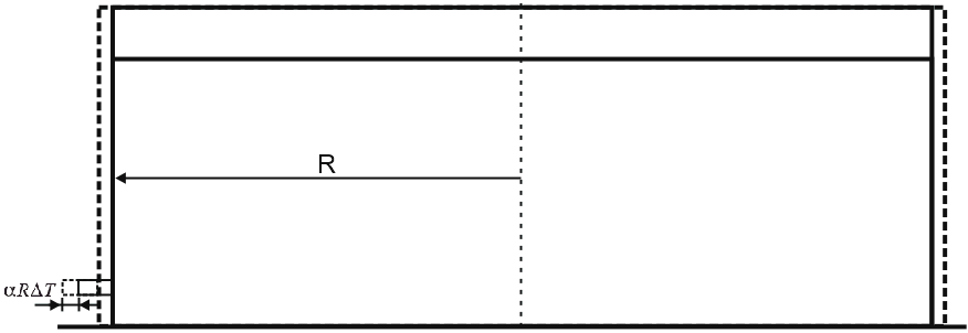
Large tank diameters cause significant nozzle axial movement from thermal
expansion. Calculated as  .
PASS/START-PROF models this movement plus vertical nozzle displacement
from thermal expansion.
Large tank diameters typically preclude foundations that distribute weight over large soil areas, resulting in settlement. Settlement magnitude depends on soil type, tank weight, and dimensions per geotechnical reports. Maximum settlement occurs at tank center, minimum at edges.
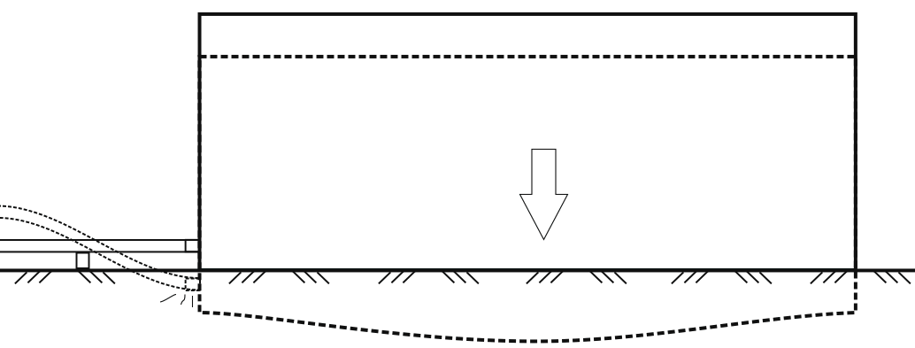
Piping connected to tank shell nozzles must account for settlement in stress analysis.
Reduce settlement effects by:
Position first support well away from tank nozzle
Use variable spring supports instead of rigid supports near nozzle
Install lateral or gimbal expansion joints near nozzle
Distinguish between short-term (post-filling/hydrotest) and long-term (continuous) settlement. Connect piping after short-term settlement completes. Analyze only long-term settlement.
First method works for minor settlement or large-diameter pipes with adequate self-support.
Second method may cause high nozzle loads since springs pull pipe upward and affect drainage. Manually select springs with travel range exceeding settlement and adequate capacity for pre/post-settlement reactions.
Third method increases cost and reduces service life due to expansion joints.
Model settlement in PASS/START-PROF as restraint downward movement using "From Other Influences" option.
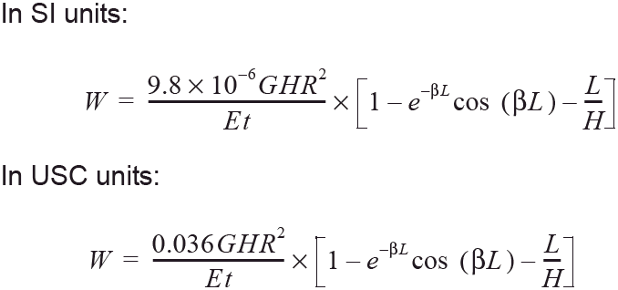
Varying liquid levels create changing shell pressure, maximum at bottom. Shell expansion at bottom constrained by tank base causes radial nozzle movement and vertical plane rotation. Significant for tanks over 36 m diameter.
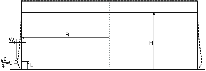
API 650 Appendix P provides shell radial growth from hydrostatic pressure:
Shell rotation from hydrostatic pressure:
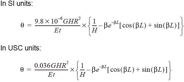
G - Design liquid specific gravity
H - Maximum filling height (mm/in)
L - Vertical distance from nozzle centerline to tank bottom (mm/in)
R - Nominal tank radius (mm/in)
t - Shell thickness at opening (mm/in)
β - Characteristic parameter, 1.285/(R*t)^0.5 (1/mm)(1/in)
E - Modulus of elasticity (MPa/lbf/in²)
ΔT - Design temperature minus ambient temperature (°C/°F)
α - Shell material thermal expansion coefficient (mm/[mm-°C]/in/[in-°F])
Reduce nozzle rotation effects by turning pipe 90° close to tank nozzle.
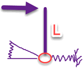
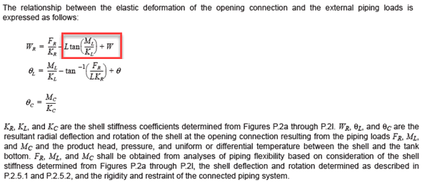
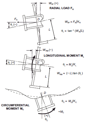
PASS/START-PROF satisfies code flexibility requirements by creating rigid element length L, connecting tank nozzle to upper end, and applying flexible springs KR, KL, KC at lower end.
Two methods calculate allowable loads.
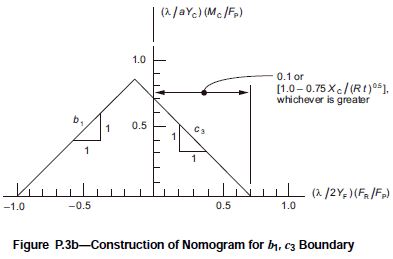
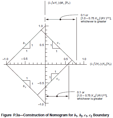
First method per API 650. Allowable moment (ML, MC) and axial force (FR) envelopes:
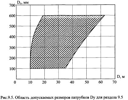
Second method per STO SA 93-002-2009. Allowable moment and axial force envelopes:
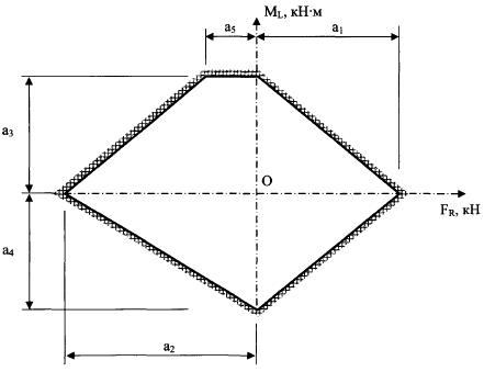
Applicable when D and DN values fall within specified envelope:
To insert tank nozzle, select the desired node and use: Insert > Equipment > Tank Nozzle