
Learn about START-PROF pipe stress analysis software
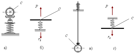
These supports use springs or spring assemblies to accommodate thermal expansion and control pipe stress through spring compression forces. Variable spring supports mount below the pipe (fig. 1a), while variable spring hangers suspend from above (fig. 1c).

Fig. 1
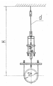
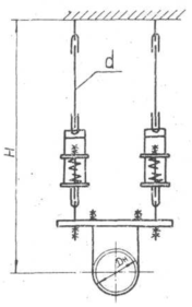
A variable spring support can have one or more vertical spring assemblies, see fig. 2. Select the number of assemblies based on space constraints. Each assembly can stack multiple springs.


Fig. 2
Ignoring hanger tilt and friction effects, both configurations behave identically (fig. 1b and 1d). For analysis, we'll assume a single spring.
The support acts as a linear vertical spring restraint. The upward reaction force has two components
 ,
,
where
Ps - preload force from initial spring compression during installation (preload force),
rz - spring reaction to pipe displacement at point C, equal to stiffness times displacement rz = λ ·Δ.
The spring must remain compressed at all times. This allows variable spring supports to function as double-acting restraints. If analysis shows spring tension, the software displays a warning message.
Preload force Ps is the concentrated force from compressing spring supports off-pipe. Ps is determined by the spring support pre-tensioning method.
The operating and cold loads on the spring (Rop and Rcold) vary with operating conditions. But the preload value remains constant. This lets you reuse springs while modifying the pipe design. For different analysis cases like Equipment Nozzle Load Check or transportation analysis, convert springs to custom restraints.
Springs fall into two classes: Class 1 allows 70mm maximum travel (operating deflection) and Class 2 allows 140mm maximum travel. "1+2+2" denotes one Class 1 spring and two Class 2 springs in series.
In this example, the assembly structure is 1+2+2=5, with total allowable travel of 5*70 = 350mm. Spring codes follow industry standards specified in Project Settings.
Flexibility describes the elastic behavior of a spring support or hanger with one or more spring assemblies. Total travel λ depends on the number of springs and their individual flexibility. In the example above, total flexibility is
l= l70 + l140 + l140
Class 2 spring flexibility (l140) is twice that of Class 1 springs (l70). l140 = 2·l70. Thus, total flexibility equals:
l=5·l70
Stiffness K is the inverse of flexibility
K=1/l
Ideally, the pipe should respond to thermal expansion like a weightless spring. Spring support compression is set to counterbalance the heated pipe's weight. At each support point, spring reactions should produce zero vertical displacement from weight loads [1].
Proper spring selection requires:
1. Load variation between operating and cold conditions must not exceed 25%
Variation=(Rop-Rcold)/Rop*100%≤25%
Achieve this by selecting appropriate spring stiffness λ. Lower stiffness makes this condition easier to satisfy. With large visible displacement Δvis, you may need to replace the spring with a constant support. Two types of visible displacement exist:
Inst-Ope: Δvis = Δinst - Δop = (Rinst - Rop)·l·n
Ope-Cold: Δvis = Δop - Δcold = (Rop - Rcold)·l·n
2. Spring allowable load must exceed both Rop and Rcold.
n - number of spring assemblies
For cold mode spring selection, swap cold and operating loads in the formulas.
START-PROF selects springs in two steps:
Step 1: Replace all springs with rigid unidirectional supports. Apply weight loads only. Determine maximum operating spring loads Rmax=Rop/n. Select springs with allowable load exceeding Rmax from the database.
Step 2: Add stiffness from selected springs. Apply thermal and displacement loads only. Determine operating displacements Δop. Calculate maximum spring load Rmax=Rop/n if Δop≤0 and Rmax=(1+Variation/100%)·Rop/n if Δop>0. Calculate minimum stiffness λ = (Variation/100%)·Rop/(Δop·n). Select springs with allowable load exceeding Rmax and stiffness less than l.
Variation=(Rop-Rcold)/Rop*100% - load variation between cold and operating conditions.
Step 2 repeats until spring selection stabilizes.
See the table below:
# |
Name |
Load case |
Allowable stress |
Frict. factor |
Spring |
Output |
L1 |
Hanger selection |
W1 |
- |
0 |
Unidirectional rigid |
|
L2 |
T1+D1 |
- |
0 |
Stiffness from table (iteration procedure) |
START-PROF can select:
Automatic spring support selection follows [1]. For manual control of forces and stresses, input reaction forces and flexibility directly. Manual adjustment can yield more economical results than automatic selection per [1]. Manual adjustment of spring support forces is often necessary to reduce equipment nozzle loads. Use the transfer function to copy automatically calculated spring properties to input data for manual editing.
Spring selection can use two conditions (set in Project Settings):
For high-temperature pipelines (Тop>3500), select and adjust springs for operating conditions (using two-step compression or pre-tensioning). For low-temperature pipelines (Тop≤3500), use single-step installation, and select springs for cold conditions.
Note: START-PROF selects springs per [1] assuming linear behavior (no friction, pendulum effects, etc.), then analyzes the pipe with nonlinear effects. Thus, the calculated load variation may exceed the selection input value. In this case, input a lower variation and re-analyze.
The table below shows input and calculated spring support loads based on the selection condition.
Pipe condition during spring selection, set in Project Settings |
Description |
Spring support reaction forces |
|
|---|---|---|---|
input value |
calculated value |
||
Cold |
No spring preload Ps selection. The software calculates reaction forces for all operating conditions, including preload Ps. |
Rcold |
Rop, Rassembly, Ps |
Operation |
No spring preload Ps selection. The software calculates reaction forces for all operating conditions, including preload Ps. |
Rop |
Rcold, Rassembly, Ps |
No spring selection |
Analysis with known spring properties (model springs as custom restraints) |
Ps |
Rop, Rcold, Rassembly |
Operation |
Spring preload Ps is automatically selected for zero displacement from weight loads in the operating condition |
0 |
Rop, Rcold, Rassembly, Ps |
Cold |
Spring preload Ps is automatically selected for zero displacement from weight loads in the cold condition |
0 |
Rop, Rcold, Rassembly, Ps |
Spring support loads in all conditions must not exceed the allowable load Rmax with safety factor m [1].
m∙Rop
≤
Rmax
m∙Rcold
≤
Rmax
m - safety factor set in spring properties.
The software automatically selects springs so that loads Rop and Rcold do not exceed the allowable load Rmax. For manual input forces, the software checks and displays messages. If springs are modeled as custom restraints, you must manually verify allowable load requirements.
For support pre-tensioning, meet this condition:
m∙Ps ≤ Rmax
The software does not check this condition automatically!
For two-step compression or lift-off method, no "pre-tensioning" state exists, so no allowable load check is needed.
Use for spring selection in both cold and operating conditions.
1. Free spring height is Hfree, with zero compression force Rfree=0.
2. Pre-compress the spring off-pipe (e.g., on the floor) using a jack. Compress to the preload force Ps. The corresponding height is Hs. Lock the compression with temporary ties welded to the spring housing. Install the spring on the pipe resting on temporary rigid supports, and remove all gaps (by adjusting rod length, adding shims, etc.). Support load is Rs=0, spring compression force is Ps and spring height is Hs. This is the installation state before spring adjustment.
3. Cut the temporary ties. The pipe immediately displaces by Δassembly, moving to the installation state after spring adjustment. Now both the spring support and the pipe act as springs. Installation support load is Rassembly, and spring height is Hassembly.
Rassembly= Ps
- Δassembly/λ
Hassembly
= Hs + Δassembly
4. After filling and heating the pipe to operating temperature, displacement from the "original" state is Δop, support load is Rop and height is Hop.
Rop= Ps
- Δop/λ
Hop
= Hs + Δop
5. After cooling and depressurizing, displacement from the "original" state is Δcold, support load is Rcold, and spring height is Hcold.
Rcold= Ps
- Δcold/λ
Hcold
= Hs + Δcold
Negative signs occur because START-PROF uses consistent positive directions for concentrated forces and linear displacements.
Rop and Rcold - spring support reactions in operating and cold conditions. Knowing these forces and support flexibility l, calculate visible pipe displacement between cold and operating conditions:
Δvis = |Δop - Δcold| = |Hop - Hcold| = | λ (Rop - Rcold)|
Use for spring selection in cold condition.
Gradually lift the pipe from temporary rigid supports using spring compression. The resulting spring compression creates reactions that balance the pipe weight.
For low-temperature pipes, spring thermal displacement is small compared to high-temperature pipes, so further compression is unnecessary.
No need to select spring height Hassembly values. Stop compression once the pipe lifts off the temporary supports. This method eliminates height Hassembly analysis inaccuracies.
For this analysis type, select springs for cold conditions. Actual installation forces Rassembly and displacements Hassembly should theoretically match design values from the zero weight displacement condition in cold conditions (cold weight balance). Differences may occur due to modeling inaccuracies (model vs. actual structure differences).
Use for spring selection in operating condition.
Lift the pipe from temporary rigid supports using spring compression. Remove the temporary supports and continue compression until reaching design height Hassembly and force Rassembly.
In this case, installation springs are "over-compressed". After heating, thermal displacement occurs, operating force becomes Rop, and height becomes Hop. Pipe weight in operating condition is balanced, since spring selection ensures zero displacement from weight loads in operating condition (operating weight balance).
1. RTM 24.038.12-72 Variable spring hanger selection for nuclear and power plant piping. Ministry of Heavy, Power and Transport Engineering. Moscow 1973
2. D. Kostovetsky, B. Tokarski. On spring support preloading. CKTI Proceedings. Pipeline Design and Calculation for Power Plants. Issue 67, Saint Petersburg, 1966
3. V. Nakhalov. Spring Support Adjustment for Power Plants, Moscow 1975