
Constant spring supports are increasingly popular alternatives to variable spring supports. They are modeled as rigid rod hangers with rotating blocks and applied loads P (Fig. 1). Supporting force P remains constant during vertical displacement. This theoretical configuration is impractical due to excessive size requirements.
Fig. 1
Modern constant spring supports use spring-lever mechanisms (Fig. 2), where pre-load adjustments maintain nearly constant supporting force within specified vertical travel ranges (Fig. 3).
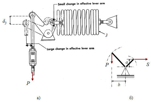
Fig. 2
Fig. 3
This support type does not require external restraints. Supporting force is applied at the support node through three components in global coordinates Fx, Fy, Fz. See "Custom Restraints"
Property |
Description |
Name |
Element identifier. When checked, displays in 3D view. |
Weight |
Weight of the support component attached to the pipe. This weight is applied at the attachment node. When building structure load capacity is specified, the calculated load includes both piping weight and support weight. When support load capacity is specified, either omit support weight or increase allowable load by the support weight value. |
Series |
|
Rod number |
Number of parallel hanger rods (1 or 2) |
Support number |
Number of parallel supports (1 or 2) |
Rod length |
Rod length used for pendulum effect calculations |
Test state mode |
Accounts for temporary spring locking during system testing |
Friction factor |
|
Force along the X axis |
Support force component along global X axis. Automatic rod selection not available |
Force along the Y axis |
Support force component along global Y axis. Automatic rod selection not available |
Force along the Z axis |
Support force component along the global Z axis. Automatic constant spring selection occurs when set to 0. |
To insert this element, select the target node and use: Insert > Insert Restraint > Constant Spring Support / Insert > Insert Restraint > Constant Spring Hanger
or click the  toolbar icon.
To view element properties:
Double-click the element in the 3D view
Select the
element and click the  toolbar icon