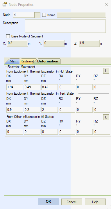

Input support displacements and rotations only along active restraint directions. Apply linear displacements along linear restraints and rotational displacements along rotational restraints.
For detailed configuration, see load combinations.
Account for equipment thermal expansion displacements only in the operating state. PASS/START-PROF applies appropriate stress intensification and range reduction factors for high-temperature analysis.
Account for equipment thermal expansion displacements only in the test state.
Support displacements from other sources apply to all three analysis states (operating, test, and cold), modeling effects such as support settlement. These displacements exclude stress intensification and range reduction factors in high-temperature analysis.
For configuration details, see load combinations.
Figure 1 demonstrates modeling column equipment thermal expansion effects on connected piping. Input support displacements at node 2: Z-axis displacement Δ2z=α(Top-Tassembly)L2, Y-axis displacement Δ2y=α(Top-Tassembly)×D/2; and nozzle displacement at node 4: Z-axis displacement Δ4=α(Top-Tassembly)L4, where α = equipment material thermal expansion coefficient, Top = operating temperature, Tassembly = installation temperature, L2,4 = distance between top restraint and equipment anchor point.

Figure 1. Modeling column equipment thermal expansion effects on piping
| Property | Description |
Displacement |
Linear displacement components along global coordinate system axes X,Y,Z |
Rotation |
Rotation angle components about global coordinate system axes X,Y,Z |
Insert > Displacement > Move and Rotate Restraint