

Learn about PASS/START-PROF pipe stress analysis software
Slug flow loads are calculated using PASS/Hydrosystem and exported to PASS/START-Prof for stress analysis. The workflow is as follows:


Slug impact on bends and tees generates significant dynamic loads that can cause piping detachment from supports, exceed allowable nozzle loads, and damage equipment.
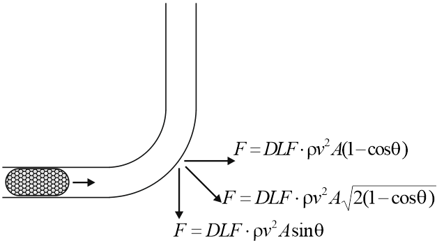
The static method calculates slug flow forces using these formulas:
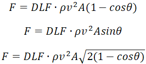
Where:
F - Dynamic load (N)
 -
Bend angle (90°, 45°, etc.)
 -
Fluid density (kg/m³)
v - Slug velocity at impact (m/s)
A - Internal pipe cross-sectional area (m²)
DLF - Dynamic load factor (recommended DLF=2 for static analysis)
For straight tees, calculate loads as for 90-degree bends.
Apply calculated forces sequentially to each bend where slug impact occurs.
Sample project: SlugFlow.ctp
Input data:
Pipe diameter: 0.219 m
Pipe wall thickness: 0.016 m
Fluid: Steam + water
Velocity: 12.65 m/s
Water density: ρ=1000 kg/m³
Calculation:
A=π∙(D-2t)²/4 = 3.14159∙(0.219-2∙0.016)²/4 = 0.027465 m²
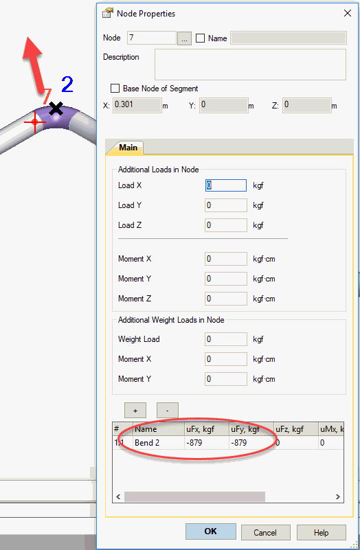
Bend 2 loads:
F=DLF*ρ*v²*A*(1-cos 90)=2*1000*12.65²*0.027465*(1-0)=8790 N (879 kgf)
F=2*1000*12.65²*0.027465*sin 90=8790 N (879 kgf)
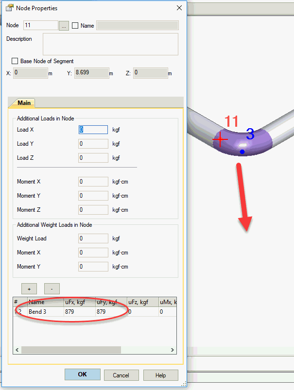
Bend 3 loads:
F=DLF*ρ*v²*A*(1-cos 90)=2*1000*12.65²*0.027465*(1-0)=8790 N (879 kgf)
F=2*1000*12.65²*0.027465*sin 90=8790 N (879 kgf)
Bend 4 loads:
F=DLF*ρ*v²*A*(1-cos 60)=2*1000*12.65²*0.027465*(1-0.5)=4395 N (439 kgf)
F=2*1000*12.65²*0.027465*sin 60=7610 N (761 kgf)
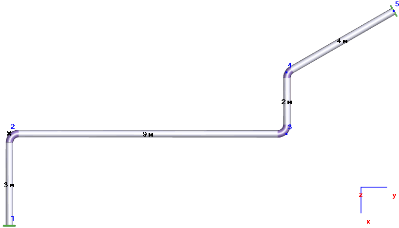
Smaller bend angles produce lower slug impact loads due to reduced flow direction change.
Using the load case editor, create one main operating mode (1) and three additional modes for slug impacts at bends 2, 3, and 4 (1.1, 1.2, 1.3). Set mode type to occasional.

Three load modes are shown below:
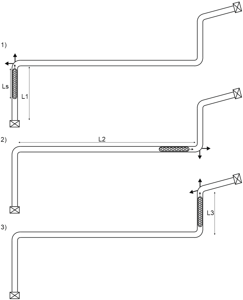
Add nodes near bend 2 and apply calculated loads:
Bend 3 loads:
Bend 4 loads:

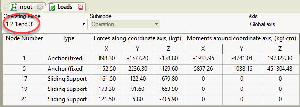
Support reactions from slug impact at bend 3:
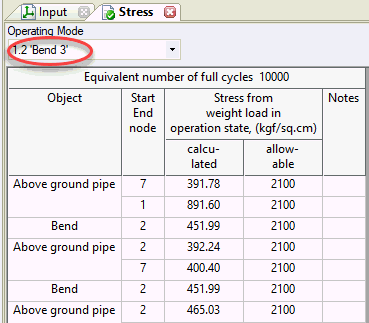
Pipe stresses from slug impact at bend 3:
To prevent piping detachment and reduce loads:
- Install limit supports (limit stops with gap, sway braces, snubbers) to absorb dynamic loads
- Modify piping layout to minimize bend angles
- Eliminate slug flow conditions where possible