This table displays displacement results for all nodes in the piping model. The table content and format depend on four configuration settings:
Setting |
Description |
Operating Mode |
Select the operating mode for result display
Maximum - displays the maximum value from all operating modes in each cell View analysis results for force-based loadings, seismic, wind, and ice loading conditions |
Submode |
PASS/START-PROF calculates multiple submodes (piping states) for each operating mode
For detailed information, see load combinations. |
Occasional Loads |
|
Coordinate System |
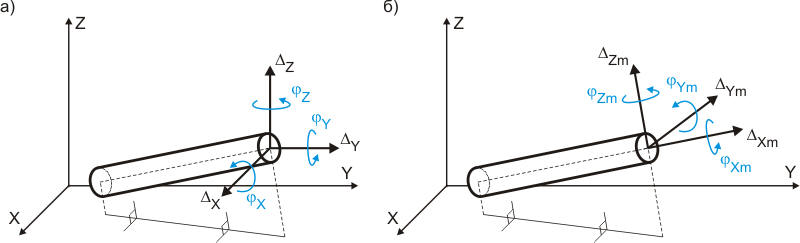
Linear and rotational displacements are displayed as projections on coordinate systems:
Fig. 1. Node displacement in global and local coordinate systems |
Displacement Type |
Filter display to show linear displacements only, rotational displacements only, or both |
Element Filter |
Display displacements for all nodes, or filter to show only supports and hangers, only valves, or only bends |
Since bend angles are not physically
defined at element intersection points, displacements for elbow nodes
are displayed at the bend midpoint.
Linear displacements are positive when
aligned with coordinate axis directions. Rotation
angles are positive counter-clockwise when viewed from the axis end.
After analysis: Output > Displacement