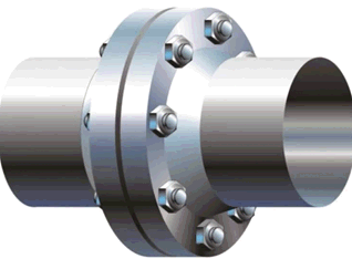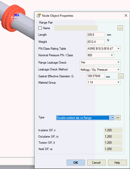


Model flange pairs similar to valves. Flange weight calculation follows the same method as valves. Enable flange leakage analysis by selecting the "check leak resistance" option.


Property |
Description |
Name |
Element identifier. When selected, displays in 3D model view. |
Length, H |
Total assembly length of flange pair |
Weight |
Flange pair assembly weight including bolts and nuts. Excludes insulation and fluid content weight. Fluid and insulation weights automatically calculated from adjacent piping data. |
Flange Leakage Check |
Enable flange leakage analysis when selected |
Leakage Check Method |
Select flange leakage analysis methodology Insulation joint (Insulation Kit) stress evaluation follows manufacturer specifications using 72% or 75% of yield stress allowable:
72% yield stress equation:
75% yield stress equation:
|
Flange Code |
Select design standard: GOST, ASME B16.5, or EN 1092-1 |
Gasket Effective Diameter, G |
Diameter at gasket load reaction location per ASME B16.20 & ASME Section VIII Division 1, Appendix 2, Table 2-5.2 For ASME B16.5 and EN 1092-1 flanges, calculate G using:
OD – Gasket outer diameter ID – Gasket inner diameter b0 - Basic gasket seating width (ASME VIII Div. 1, Appendix 2, Table 2-5.2) b – Basic gasket width
Cb = 0.5 (U.S. customary units), 2.5 (SI units)
|
Nominal Pressure PN / Class |
PN rating for GOST and EN 1092-1 flanges, Class rating for ASME B16.5 flanges |
Material Group |
Flange material classification per selected standard ASME B16.5-2020
EN 1092-1:2013
|
Factor Fm |
Fm factor for Code Case 2901 (PVP) method
|
Bolt Area, Ab Bolt Circle Diameter, C |
|
Bolt Material |
Select material from database |
Insert flange pair at selected node using: Insert > Insert Flange Pair
or click toolbar icon: 