Read about START-PROF pipe stress analysis software

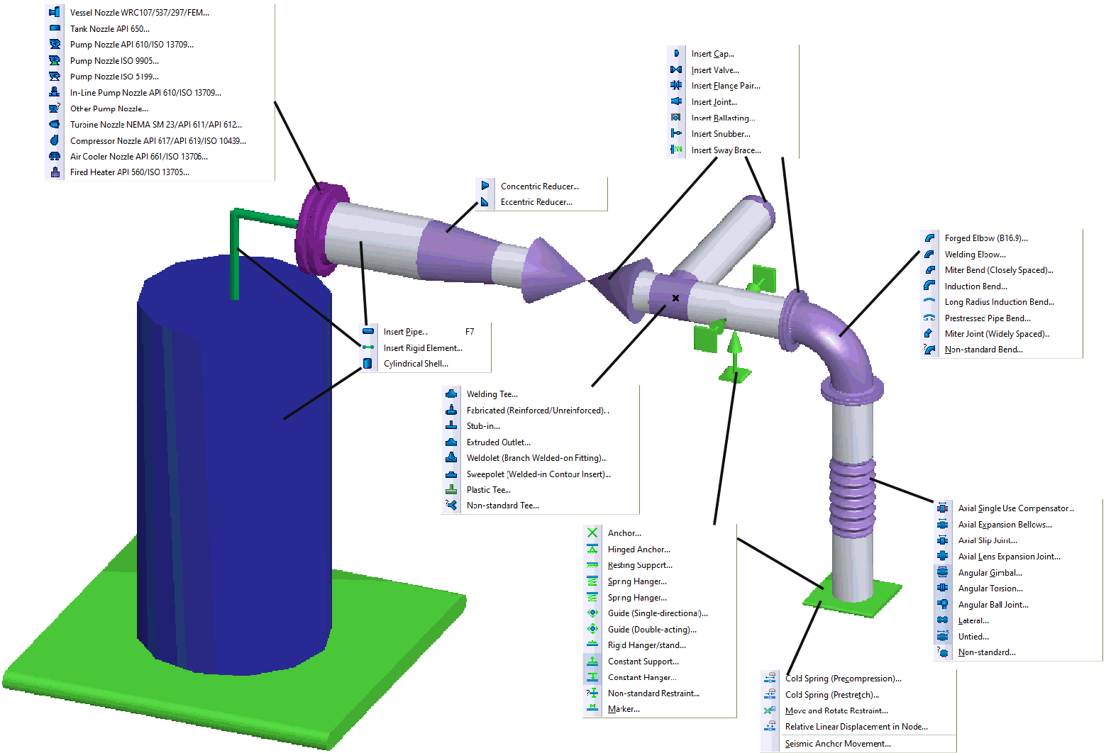
A piping system is modeled using beam elements including straight pipes and bends. Nodes connect elements and accommodate various components. The piping model represents a simplified structural system, eliminating characteristics irrelevant to stress analysis. Different models can represent the same physical piping depending on analysis requirements. Structural mechanics methods for elastic linear rod systems form the analysis basis.
The model must:
Reflect potential deformations and structural damage based on practical experience
Accurately represent structural elastic properties under load
Place the structure under more severe conditions than actual (ensuring strength margin)
Remain within the theoretical limits of selected analysis methods
Selecting appropriate models requires experience and knowledge of piping analysis theories. Creating accurate models for real piping systems is a developed skill involving various techniques for different configurations. Users must understand piping deformation behavior and identify essential analysis elements.
These topics are covered in START-PROF training.
Software use does not eliminate the need for proper representation of real piping structures as analysis-appropriate models.
Before creating the pipe model for wall thickness calculations, support spacing, and expansion joint dimensions, use the START-Elements tool.
Piping model data categories:
General properties in Project Settings
Dimensional properties for pipe objects and node elements (Bends, Tees, Reducers, Expansion Joints, Flaws, valves, flanges, joints, caps, ballasting weights, etc.)
Restraints and equipment (Supports, Static Equipment, Rotating Equipment)
External forces data. Input in Project Settings and element properties. Support displacements, node deformations, and temperature cycles are specified separately.
Output reports available after analysis
For specific features see application guide
1. After creating a new project, the Project Settings dialog displays. Enter required properties and click OK.
2. The 3D view window opens for piping model creation.