
Learn more about PASS/START-PROF Pipe Stress Analysis Software


PASS/START-PROF features a comprehensive yet user-friendly soil interaction model that automates pipeline analysis with minimal user input.
The software handles diverse scenarios including dry soil burial, liquefied soil submersion, expansion cushions, insulation stiffness, ballasting weights, horizontal/vertical/inclined piping configurations, combined buried and above-ground systems, seismic wave propagation, landslides, soil subsidence, seismic fault crossings, and natural arch collapse in horizontal directional drilling.
Available soil models (selected in project settings):
Pipeline-soil interaction analysis employs methods developed by A.B. Aynbinder, based on extensive experimental and theoretical research conducted at VNIIST (Moscow) and other organizations. These methods, documented in [1] and [6], have been widely adopted across Russian and CIS companies since 1982 and integrated into five major piping stress analysis software packages in the region.
2 Buried Pipeline Model for Dry Soil
2.1 Lateral Bearing Zone #1 (Unrestrained)
2.2 Axial Sliding Zone #2 (Unrestrained)
2.3 Restrained Zone #3
2.4 Restrained and Unrestrained Zones
3 Buried Submerged Pipeline Model for Liquefied Soil
3.1 General Soil Model for Submerged Pipelines
3.2 Water Buoyancy
3.3 Liquefied Soil Properties
4.1 General Soil Support Description
4.2 Soil Support Model for Horizontal, Vertical and Inclined Pipes
5 Modeling of Soil Subsidence, Frost Heaving, Landslide, Seismic Fault Crossing
6 Longitudinal Soil Spring Properties
6.1 Bilinear Spring Model
6.2 Friction Force for District Heating Networks (EN 13941-2019, CJJ/T 81-2013, GOST R 55596-2013)
6.3 Friction Force for Gas and Oil Pipelines (ASME B31.4, B31.8, B31.12, CSA Z662, BS PD 8010, SNIP, SP, GOST)
6.4 Natural Arch of Collapse Phenomena
7 Lateral Soil Spring Properties
8 Vertical Soil Spring Properties
9 Ring Bending Stress Calculation
9.1 Ring Bending Stress from Soil Weight
9.2 Pipe Strength Against Surface Load
9.3 Polyurethane (PUR) Insulation Stress Analysis
10 Seismic Wave Propagation Analysis
11 References
PASS/START-PROF soil modeling accounts for:
The software uses a beam pipeline model with discrete bilinear springs placed at calculated intervals to simulate continuous soil interaction (Fig. 1).
1 - Vertical soil spring, 2 - Axial soil spring, 3 - Lateral soil spring
Fig. 1. Pipeline-soil interaction model
PASS/START-PROF employs two soil support placement algorithms:

This model optimizes support distribution to maximize analysis speed while maintaining accuracy.
Springs are automatically placed in three distinct zones (Fig. 2):
Pipeline, insulation, and product weights are automatically removed to prevent excessive deflections in 100D spans. These weights are used to calculate soil spring properties and friction forces.
Heavy components like valves are considered separately and will produce visible deflections:
Additional supports can be added without affecting soil model accuracy:
Spring density can be manually increased for enhanced accuracy:
When multiple operating modes are specified in the operation mode editor, La and Lb values from the first sustained operating mode apply to all modes.
Support density automatically increases in high-displacement regions including:
Fig. 2. Soil interaction support placement
Support placement on long radius bends
Zone #1 experiences significant bending deformations and transverse displacements (Fig. 3). Four soil springs are automatically placed here for accuracy.
Lateral bearing length is automatically calculated using:
 ,
,
where
 -
pipe bending stiffness,
-
pipe bending stiffness,
 -
soil stiffness factor.
-
soil stiffness factor.
Fig. 3. Bend Zone #1
Zone #2 exhibits substantial longitudinal deformations and displacements (La in Fig. 4). Supports are placed with exponentially increasing spacing from Zone #1 to Zone #3.
See also Restrained and Unrestrained Zones

Virtual anchor length for elastic-plastic soil model [6] is calculated using:
Fig. 4. Sliding Zone #2
Zone #3 experiences minimal bending and axial displacements. Soil springs are spaced at 100D intervals.
See also Restrained and Unrestrained Zones
ASME B31.4, B31.8, B31.12, CSA Z662, and BS 8010 codes distinguish between "Restrained" (#3) and "Unrestrained" zones with different strength criteria, unlike EN 13941, GOST, SNIP, and SP codes which use universal criteria. PASS/START-PROF automatically identifies virtual anchor points and zone boundaries, eliminating manual determination. Learn how PASS/START-PROF handles this.
For submerged buried pipelines, PASS/START-PROF places soil springs at 5D spacing. Pipeline, insulation, and product weights are retained for accurate ballasting analysis. Ballasting weights can be added to the pipeline:
Buoyancy forces are automatically calculated based on water level. For horizontal, vertical, and inclined pipes, buoyancy applies only to submerged sections (Fig. 5).
Fig. 5. Displaced liquid volume calculation for buoyancy analysis
PASS/START-PROF automatically calculates liquefied soil properties (suspended soil particles in water). See soil spring property descriptions below.
Each soil support consists of vertical, horizontal, and longitudinal springs (Fig. 6).
Fig. 6. PUR insulation stiffness and expansion cushion pad accounting
Stiffness K1 is a non-linear function of expansion cushion deformation according to [3]. Expansion cushion presence is set in buried element properties.
Stiffness K2 is a non-linear function of polyurethane foam (PUR) layer deformation according to [3]. Insulation casing diameter must be specified in buried element properties for PUR stiffness calculation.
Soil spring stiffness varies by direction (Fig. 6):
Reaction-displacement algorithms are shown in Fig. 7. Values are calculated based on buried element properties and soil properties from the soil database.
Lateral displacement springs K3 follow the reaction-displacement relationship in Fig. 7.a. Vertical and longitudinal springs are shown in Fig. 7.b and Fig. 7.c respectively, according to [1] and [6].
During analysis, PASS/START-PROF performs iterative calculations to refine spring stiffness values K1, K2, K3, K4 and K5. Analysis terminates when specified accuracy is achieved.

Fig. 7. Bilinear soil resistance vs displacement diagrams for K3, K4, K5
Depth, water height, and subsidence can vary along pipe length.

Users specify properties at pipe ends: ZH, HBH, ΔH and ZK, HBK, ΔK (Fig. 8).
Note: Depth, water height, and subsidence are node properties, not element properties. These values must be consistent for shared nodes between adjoining elements.

Fig. 8. Depth and water height variation along element length
For inclined and vertical pipes, each soil spring's bilinear properties (stiffness, buoyancy, displacement, etc.) are calculated using individual spring depth (Fig. 9). Depth Zi and water height HBi values are linearly interpolated between start and end nodes ZH and ZK (Fig. 9) when calculating K3, K4 and K5 stiffness. Buoyancy is calculated based on local water height HBi. Subsidence (spring displacement) Δi is similarly calculated using linear interpolation between ΔH and ΔK.
Fig. 9. Spring depth calculation
Spring stiffness K3, K4 and K5 also depends on pipe inclination angle (0 to 90 degrees). For vertical pipes, vertical stiffness K4 behavior matches horizontal spring K3. With expansion cushions, spring stiffness K1 is added to vertical spring K4.
PASS/START-PROF efficiently analyzes complex piping configurations including:
Soil subsidence from base soil thawing or mining eliminates pipeline base resistance, causing pipeline settlement with the soil (Fig. 10).


Fig. 10. Pipeline with soil subsidence and frost heaving
Subsidence is modeled by shifting the vertical resistance diagram left by the subsidence value Δ (Fig. 11). This is equivalent to downward soil support displacement by distance Δ (Fig. 10).
Subsidence magnitude from base soil melting or compression is determined using code methods (e.g., SNiP [5]) or specialized software like BOREY, FROST 3D.
Model soil subsidence by specifying -Z direction soil movement in pipe buried properties.
Model frost heave (upward displacement) by specifying positive +Z direction movement.
Fig. 11. Soil resistance to vertical displacement with subsidence
Model landslides, permanent ground deformation, vertical/horizontal seismic fault crossings by specifying soil displacement in all directions (X, Y, Z) in pipe buried properties.


PASS/START-PROF provides strain limit criteria per ASCE 2001 ALA and other codes for pipeline strength verification during landslides, selectable in the operation mode editor.

PASS/START-PROF soil database contains all necessary values for soil spring property calculation.
Soil resistance to longitudinal pipe displacement in elastic-plastic deformation regions is modeled as linear correlation proposed by A.B. Aynbinder [1].

where
F - maximum allowable soil resistance to displacement, N/cm² (longitudinal friction force, see calculation methods below)
cx0 - generalized tangent soil resistance factor N/cm³,
∆t - working displacement value corresponding to maximum soil resistance, cm.
This relationship substitutes the actual soil resistance diagram (Fig. 12.a) with an idealized bilinear diagram (Fig. 12.b).
Fig. 12. Soil resistance to longitudinal displacement
Tangent soil resistance factor is:

and has soil bed factor dimensions. In the soil database, this value is the resistance to longitudinal displacement factor, representing the slope of the bilinear diagram's first section (Fig. 12.b).
For rigid-plastic soil models without elastic resistance, use very high cx0 values (Fig. 13). Practical values around 100,000 tf/m³ can be used. If cx0=0 in the database, PASS/START-PROF uses 100,000 tf/m³.

Fig. 13. Elastic-plastic and rigid-plastic soil models
Experimentally derived cx0 values for various soil types are provided below.
Generalized tangent soil resistance factor cx0 values, kgf/m³
Soil Type |
Liquidity Index IL |
Porosity Factor ε |
||||
|---|---|---|---|---|---|---|
<0.5 |
0.5-0.6 |
0.6-0.7 |
0.7-0.8 |
>0.8 |
||
| Coarse and medium gravel sand | - | 330000 | 300000 | 270000 | 250000 | - |
| Fine and silty sand | - | 250000 | 210000 | 210000 | 190000 | - |
| Sandy loam | 0 < IL ≤ 0.25 | 350000 | 330000 | 300000 | 300000 | 300000 |
| 0.25 < IL ≤ 0.75 | 350000 | 320000 | 300000 | 250000 | 250000 | |
| Loam | 0 < IL ≤ 0.3 | 380000 | 350000 | 350000 | 320000 | 300000 |
| 0.3 < IL ≤ 0.75 | 350000 | 330000 | 300000 | 250000 | 200000 | |
| Clay | 0 < IL ≤ 0.3 | 400000 | 380000 | 350000 | 330000 | 300000 |
| 0.3 < IL ≤ 0.75 | 450000 | 400000 | 350000 | 300000 | ||
Open trench installation uses full soil depth for pressure calculations. Friction force is calculated using classical equation:

Soil pressure increases linearly with depth.
Trenchless methods like horizontal directional drilling at significant depths create self-supporting arch collapse above the pipe (natural arch of collapse).

This arch supports overlying soil pressure.
Only soil within the natural arch exerts pressure on the pipe. PASS/START-PROF automatically considers natural arch collapse for friction force, polyurethane foam insulation stress analysis, and ring bending stress calculation using reduced depth based on calculated arch dimensions.


Bi-linear soil spring diagram matches Aynbinder's model with different notation.
f factor specified in pipe properties as "insulation adhesion factor, nm"
Kq and Kc are soil pressure coefficients
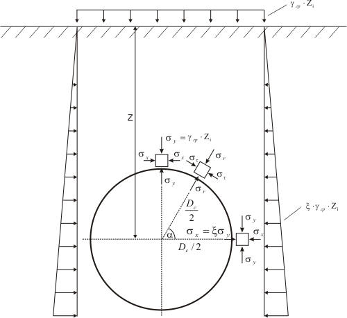
PASS/START-PROF automatically calculates ring bending stress from soil weight.
Ring bending stress calculation considers:
Soil weight
Surface loads (vehicles, buildings, etc.)
Internal pressure
Pipe ovality
Ring bending stress is verified against allowable values per applicable codes (ASME B31.4, B31.8, etc.).
See details here
PASS/START-PROF calculates pipe strength against surface loads including:
Vehicle loads
Building foundations
Equipment loads
Other surface pressures
Surface load distribution through soil is calculated using Boussinesq's theory.
Surface loads can include two concentrated forces and uniform line loads. See details here

For district heating networks with PUR insulation, PASS/START-PROF calculates:
Carrier pipe stress
Insulation casing stress
Interaction between carrier pipe and casing
PUR insulation stress analysis follows EN 13941 and AGFW FW 401 requirements.
See details here
PASS/START-PROF performs seismic analysis for buried pipelines subjected to seismic wave propagation.
Seismic analysis includes:
Wave propagation effects
Soil-structure interaction
Pipeline strain verification
Anchor force calculation
Seismic analysis methods comply with ASCE 2001 ALA guidelines and other international standards.
Seismic wave propagation effects on buried pipelines are described here
1. Aynbinder A., Kamerstein A. Analysis of the transmission pipelines for strength and stability. Moscow "Nedra". 1982
2. Skomorovsky Ya.Z., Ainbinder A.B. Longitudinal movement of buried pipelines taking into account physical nonlinearity soil shear resistance. Pipeline strength questions, Moscow 1975
3. Arbeitsblatt FW 401: Verlegung und static von KMR für Fernwärmenetze Arbeitsgemeinschaft Fernwärme- AGFW-e, V.- bei der Vereinigung Deutscher Elektrizitätswerke, 1992
4. Borodavkin P. Buried transmission pipelines (design and building), Moscow "Nedra", 1982
5. SNiP 2.02.04–88. Foundations located on permafrost. Gosstroy USSR. Moscow, 1991
6. Aynbinder A., Kamerstein A. Analysis of the transmission pipelines and flowlines for strength and stability. Moscow "Nedra", 1991