

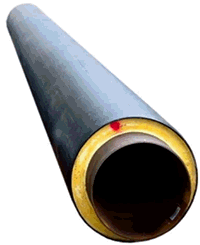
1 - backfill soil, 2 - expansion cushion, 3 - foundation soil
Figure 1
Axial stress σz in PUR insulation is calculated as:

where:
σ - axial stress in steel pipe (from bending and axial force)
Е - elastic modulus of steel pipe
ЕPUR - PUR elastic modulus
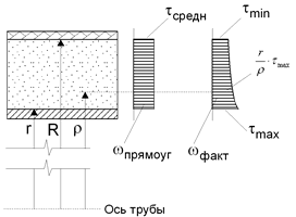
Maximum shear stress along the pipeline axis τyz due to polyethylene shell friction against soil at the PUR layer interface equals:

where qfr - longitudinal friction force, Dc - PE casing diameter
Radial σy, circumferential σx, and shear stresses τxy in the PUR layer are analyzed using START-PROF's finite element engine. A 1cm ring section in plane strain state is evaluated at 5 circumferential positions (Figure 2).


1 - foundation soil, 2 - polyethylene casing, 3 - foamed polyurethane, 4 - steel pipe
Figure 2
Maximum shear stress τxy occurs at the inner PUR layer:

Soil pressure comprises vertical and horizontal components. Vertical load equals soil pressure at burial depth, applied to the top pipe half, while foundation soil reaction acts on the bottom half. Horizontal load follows trapezoidal distribution, equaling vertical pressure multiplied by lateral pressure coefficient (Figure 4).
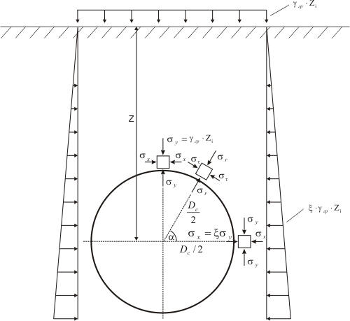
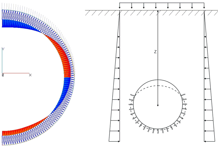
Figure 4
For open trench installations, soil arching is neglected. Soil pressure increases linearly with depth.
For trenchless installations at significant depths, a natural soil arch forms above the pipe, supporting overburden pressure. Only soil within this arch exerts pressure on the pipe.


Soil is modeled as discrete compression-only springs around the PE casing finite elements. Springs deactivate under tension. Soil detachment typically occurs at the pipe crown due to cross-section ovalization, rendering top springs inactive.
Internal and hydrostatic pressures apply radially to the pipe perimeter. The finite element analysis includes geometric nonlinearity, accounting for pressure-induced ring stiffening.
Five stress tensor components are calculated: σx, σy, σz, τyz, τxy, τxz=0 (Figure 5). Equivalent stress follows maximum shear stress theory as the difference between first and third principal stresses:

where σ1 and σ3 are roots of:


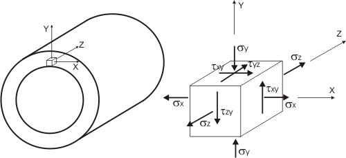
Figure 5
Equivalent and shear stresses are evaluated at 5 PUR insulation locations A, B, C, D, E (Figure 6)
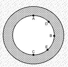
Figure 6
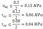
Per EN 13941 7.3.1-7.3.2, EN 253 4.5.5.2, and GOST 55596, equivalent stress and circumferential/longitudinal shear stresses are verified to ensure PUR layer strength and steel pipe adhesion. Allowable stress for PE casing is 12 MPa.
The analysis solves nonlinear equations accounting for soil detachment at the pipe crown and internal pressure effects (including geometric stiffness). Convergence issues may arise from:
Insufficient pipe wall thickness causing stability loss under soil pressure. System issues warning for inadequate wall thickness.
Inadequate foundation soil bearing capacity leading to unstable pipe equilibrium. Increase foundation stiffness to ensure stability.
See also Ring Bending Stress Calculation
1. Alexandrov A.V., Magalif V.Y., Matveev A.V., Stress analysis of foamed polyurethane insulation, «Pipelines and ecology», 2003, №3, ZAO «NPO Stroypolimer»
2. GOST 30732-2006, Steel pipes and fittings with foamed polyurethane insulation in polyethylene casing, Gosstroy of Russia, 2006
3. GOST 55596-2013 District Heating Network Stress Analysis