Icon |
Name |
Description |
|---|---|---|
|
Element |
Insert above-ground pipe element |
|
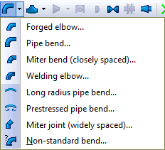
Bend |
Insert pipe bend |
|
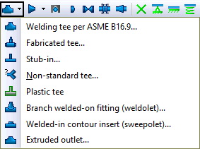
Tee |
Insert pipe tee |
|
Reducer |
Insert pipe reducer |
|
Ballasting weight |
Add ballast weight for stability |
|
Cap |
Insert pipe end cap |
|
Valve |
Insert valve |
|
Flange |
Insert flange |
|
Joint |
Insert pipe joint |
|
Restraint |
|
|
Expansion joint |
Insert expansion joint |
|
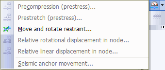
Deformation and displacement |
Apply support displacements to model equipment thermal growth or node deformations for expansion joint pre-stretch |
|
Soil |
Assign soil properties to convert between above-ground and buried pipe elements |


