Additional parameters for heat calculation
To perform heat and hydraulic calculation, in addition to modeling a pipeline, setting the pumped fluid parameters, boundary conditions for the hydraulic calculation and entering some general pipeline data and calculation results output parameters, it is also necessary to specify a number of parameters describing the heat exchange between the fluid in the pipeline and the environment. These include:
pipe wall material (mainly for non-metallic pipes)
thermal insulation parameters (for insulated pipelines)
soil parameters (for underground pipelines)
For convenience, the tabs and fields with these parameters are highlighted in a separate color (red) in the program windows.
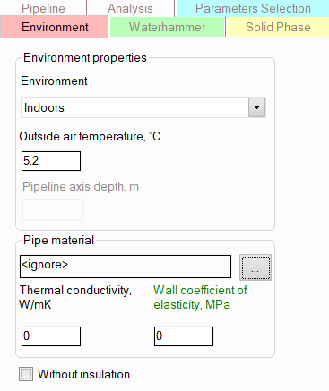
To set the environment parameters for a pipeline, select the pipeline in the project tree and then open the "Environment" tab in the Object Properties Window. The following information is specified here:
Environment - the following locations are available for the pipeline:
outdoors - for pipelines located outdoors. The outdoor air temperature is specified in the corresponding field below. Please note that specifying the wind speed is not required; during the calculation, its value is taken according to the 'worst' (from the point of view of fluid cooling along the flow) data of experimental observations;
indoors - for pipelines located indoors. The indoor air temperature is specified on the "Analysis" tab for the pipeline;
in underground duct - for pipelines located underground inside a rectangular duct, i.e. heat transfer from the pipeline to the surrounding soil is carried out through the air gap of the duct. The temperature and properties of the soil and duct in the underground location are specified on the "Soil" tab for the pipeline;
underground (without duct) - for buried pipelines in the case where the surface of the pipeline is in direct contact with the surrounding soil. The temperature and properties of the soil in the underground location are specified on the "Soil" tab for the pipeline;
in tunnel - for pipelines located in a "hot" tunnels with an average air temperature of 40°C (this temperature is fixed and cannot be changed);
underwater - for underwater pipelines. The water temperature and the depth of the pipeline axis relative to the water surface are specified in the corresponding fields below.
Pipe
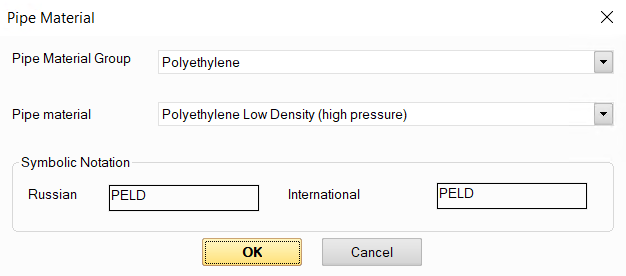
wall material - here you can either manually set the
properties of the piping wall material (thermal conductivity and coefficient
of elasticity), or select the material from a database of pipe materials
connected to the program by clicking on the button -
then the properties of the pipe material will be taken from this database:
-
then the properties of the pipe material will be taken from this database:
Please note that the thermal conductivity of metallic materials is usually quite high, especially compared to the thermal conductivity of typical thermal insulation materials (which is 3 orders of magnitude lower than that of metals). Therefore, for steel pipes (including thick-walled ones), the influence of the pipe wall on the heat exchange between the fluid in the pipe and the environment can most often be neglected. In this case, you can simply not specify the pipe material, and then the thermal resistance of the pipe wall will not be taken into account in the calculation. However, for pipes made of non-metallic materials (polyethylene, PVC, etc.), whose thermal conductivity is usually 1-2 orders of magnitude lower than that of metals, the influence of the thermal resistance of the wall on heat exchange with the environment can be noticeable. Therefore, for such materials, it can be taken into account in the calculation by specifying the wall material or manually setting its properties. In case of doubt (for example, if you are not sure what thermal conductivity the pipe wall you are planning to use has), do not forget that not taking the pipe wall into account at the heat calculation of a pipeline always goes "in reserve" (that is, when taking the pipe wall into account, heat losses will be lower than they would be without taking it into account).
If you plan to perform a waterhammer calculation for a pipeline , it is advisable to specify the wall material (or the coefficient of elasticity of the pipe material), as this will allow you to more accurately calculate the shock wave velocity for waterhammer analysis, which is especially important when calculating thin-walled pipes. If the elastic modulus of the pipe material is not specified, the shock wave velocity in the calculation is assumed to be equal to some "average" value of 1000 m/s.
Without insulation - this option is used to disable the consideration of thermal insulation at heat calculations (for example, if you want to compare the performance of an insulated and non-insulated pipeline, or if part of the pipeline is insulated, part is not, etc.). For more information on setting thermal insulation for a pipeline, see below.
Once the environmental and wall material parameters are set for a pipeline, the pipeline elements (branches, piping components) inherit the values of these parameters. If you need to model a pipeline where different parts have different environment parameters (location, air temperature, etc.) or different wall materials, see below for more information .
Thermal insulation is specified as a separate element
of the project tree. To add an insulation
layer, click the button  of Components
toolbar or use the corresponding item in
the "Insert"
menu. Note that the added thermal insulation is "applied" to
the project tree element for which it was added (which was selected at
the moment of adding the insulation), and is also hierarchically "inherited"
for subsequent project tree elements according to the following principle:
of Components
toolbar or use the corresponding item in
the "Insert"
menu. Note that the added thermal insulation is "applied" to
the project tree element for which it was added (which was selected at
the moment of adding the insulation), and is also hierarchically "inherited"
for subsequent project tree elements according to the following principle:
if insulation is added to a pipeline, it is inherited for all elements of this pipeline (branches and piping components);
if insulation is added to a branch of a pipeline, it is inherited only for elements of this branch (pipes, bends, etc.);
if insulation is added to a component of a branch (to a pipe, elbow, etc.), then it is inherited only for those components of this branch that are located in the tree after the current one (including the current one);
However, please note that if during the process of inheritance of the thermal insulation a pipeline element is encountered for which a different insulation material is specified (for example, it was specified for this element earlier), inheritance on this element is stopped, and the initial insulation material will remain for it and all subsequent elements in the project tree. For more information on inheritance of thermal insulation parameters, see below.
After adding insulation, its characteristics will be displayed in the Object Properties Window:
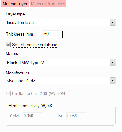
Here you need to specify the layer type (thermal insulation or cover layer), select the material from the list and specify its thickness. Please note that:
by default, materials are selected from the insulating materials database supplied with the program. When selecting a material, all its properties required for calculation are loaded automatically from this database. The main characteristics of the material can be viewed in the "Material Properties" tab of the Object Properties Window. If you want to get more information about the characteristics of this material (see its thermal conductivity coefficients, available sizes, etc.) or edit them, or if you want to add your own material to the database that is not in it (to use it in calculations), all these actions can be done using a special materials database editor supplied with the program;
to find the material more quickly, expand the drop-down list and start typing the material name on the keyboard - as you type, the list will scroll to the first material that matches the name;
it is allowed to specify no more than two heat-insulating layers. If two layers are specified, then the upper insulation layer in the project tree is considered as internal, the lower one is considered external;
the cover layer may be specified only if the heat-insulating layer is specified. Depending on the type of surface of the cover layer material, the intensity of heat transfer from this surface to the environment may differ slightly in some cases. However, most often these effects are quite small, so in practice the cover layer is often neglected, not specified or taken into account in the calculation. If the cover layer in a heat-insulating structure consists of several materials, only the outermost layer should be specified since this layer's surface determines the value of the heat transfer coefficient to the environment;
it is not necessary to specify the manufacturer of the material. It can be specified only to narrow the search area if you are looking for material from a specific manufacturer;
other elements of the insulating structure except for the thermal insulation and covering elements are not specified, since this is not required for the calculation;
if necessary, you can quickly enter the main characteristics of the thermal insulation material and calculate the pipeline with this material without adding it to the database. To do this, you need to disable the "Select from the database" option and fill in the values of heat conductivity coefficients for the "cold" (<20°C) and "hot" (>20°C) range of application for thermal insulation material, and the low emittance indicator for the cover layer materials (<= 2.33W/m2K4 for glossy covers, > 2.33W/m2K4 for matte ones).
As mentioned above, modeling of thermal insulation is only necessary for performing a heat and hydraulic calculation of the pipeline; for other types of calculations (isothermal flow analysis, diameters calculation and waterhammer calculations), specifying insulation is not required. However, if the pipeline model is planned to be exported to the START-Prof program for stress analysis, then it is recommended to specify insulation (even if you do not plan to perform a heat and hydraulic calculation in the Hydrosystem) to calculate the weights of thermal insulation, which are important to take into account at stress analysis of the pipeline.
After specifying the thermal insulation for all pipeline elements to which it was applied, a separate "Insulation" tab will be available in the Object Properties Window, which will list the specified materials and indicate their thicknesses:
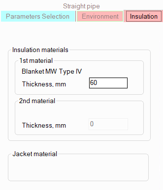
These thicknesses can be changed directly on this tab, and their new values will be inherited for subsequent elements in the project tree with the same thicknesses (however, these thickness changes will not affect previous elements in the project tree). If, starting with a certain pipeline element (branch or piping component), it is necessary to change the insulation material, you need to add a new thermal insulation layer for this element (adding materials as described above), or right-click on this element in the Project Tree Window and select the "View Insulation" item. In this case, the current insulation structure will be inserted into the tree as a descendant of the selected object, and any changes can be made to it. The new thermal insulation structure will also be "inherited" to the following elements of the project tree and elements subordinated to the current one. For more information on the inheritance of thermal insulation parameters, see below.
When specifying an underground location (in or without a duct), a separate tab "Soil" will appear in the Object Properties Window for the pipeline and its elements, where you will need to specify the soil properties and other characteristics:
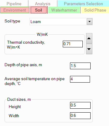
soil type/thermal conductivity -
to calculate the heat exchange of the pipeline with the surrounding
soil, it is necessary to know the value of the soil thermal conductivity.
It can be either entered manually in the corresponding field, or the
soil type can be selected in the drop-down list, and then using the
buttons  and
and  "scroll" to the soil
with the desired thermal conductivity value. If neither the soil type
nor its thermal conductivity is known, it is recommended to simulate
the 'worst' possible (in terms of heat loss) case, selecting the soil
with the highest thermal conductivity value;
"scroll" to the soil
with the desired thermal conductivity value. If neither the soil type
nor its thermal conductivity is known, it is recommended to simulate
the 'worst' possible (in terms of heat loss) case, selecting the soil
with the highest thermal conductivity value;
depth of pipe axis and the average soil temperature on pipe depth - please note that if the upper part of the pipeline (for buried pipelines without duct) or the upper part of the duct ceiling (for pipelines in ducts) is buried less than 0.7 meters, then in accordance with the recommendations of SNiP 41-03-2003, the ambient temperature in the calculation will not be the soil temperature, but the corresponding outside air temperature;
duct sizes - are set only for pipelines in ducts.
Once the soil and underground location parameters are set for a pipeline, the pipeline elements (branches, piping components) inherit the values of these parameters. If you need to model a pipeline whose different parts are located in different types of soil and/or with different laying parameters, see below for more details.
Inheritance of environmental parameters, thermal insulation, soil, etc.
In practice, there may be situations when some parts of a pipeline have one location, while others have another (for example, a pipeline from the open air goes underground, etc.); or when one part of a pipeline has thermal insulation made of one insulating material, while another part has another (or the same material but with a different thickness). In addition, for long pipelines, there are also cases when part of a pipeline is in a zone with one ambient air temperature, while another (for example, located hundreds of kilometers north or south of the first) is in another. To model such pipeline systems, it is convenient to use the inheritance of environment parameters, soils, thermal insulation structure, etc. The fact is that all environment/soil/insulation parameters specified for a pipeline are inherited by all underlying elements in the project tree. And these parameters can be changed on any element of the pipeline by selecting it in the project tree or on the diagram, opening a similar "Environment" / "Soil" / "Insulation" tab of the Object Properties Window for it and changing any characteristics there. The entered values of these parameters will be "inherited" to subsequent elements of the pipeline, so they will not have to be changed for each individual branch, pipe, etc. Inheritance occurs according to the following principle:
when changing the parameters of the environment/soil/insulation on any branch of the pipeline, these parameters will be "inherited" for this branch, all its elements, as well as all subsequent branches (and their elements) in the project tree. The parameters of all previous elements (branches, piping components) in the tree will remain unchanged.
when changing the parameters of the environment/soil/insulation for some piping component of the branch (pipe, bend, etc.), these parameters will be "inherited" only for all subsequent elements of this branch in the tree (these changes will not affect further branches in the project tree). The parameters of all previous elements (branches, piping components) in the tree will remain unchanged.
However, please note that if during the process of "inheriting" these parameters a pipeline element is encountered for which the characteristics of the environment/soil/insulation, etc. differ from the previous ones (for example, they were changed earlier on this element), inheritance on this element is stopped, and for it and all subsequent elements in the project tree the parameters of the environment/soil/insulation will remain unchanged.
Thus, in order to simulate changes in the location/insulation/soil properties, etc. during pipeline modeling, you simply need to set new location/insulation/soil parameters on the corresponding tab of the Object Properties Window for the element starting from which a particular change occurs (or add an insulation layer to this element if you need to change the thermal insulation material). However, when editing the environment/insulation/soil parameters of already modeled pipelines, you need to be careful, since when inheriting parameters, the order of the branches in the project tree becomes important. And if the order of the branches in the tree does not correspond to the order of their actual order in the pipeline, then when changing the environment/insulation/soil parameters for one branch, you can accidentally change them for the wrong branches.
Hint: to avoid confusion about the specified location conditions, soil properties, thermal insulation parameters, etc. for various pipeline elements (branches, piping components), use the filter buttons at the top of the Input Data List window:
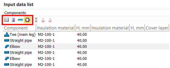
By pressing these buttons you can switch between the presentation of general parameters of branches/components (their sizes, temperatures, etc.), parameters of their location (outdoors, indoors, etc.), soil properties and thermal insulation structure. To switch between the presentation of the properties of pipeline branches and components, use the drop-down list at the top of this window or simply select the corresponding element in the project tree - a pipeline to display data on branches, any of the piping components of a branch to display data on sections of this branch.