 button of Component
toolbar (or use the corresponding Insert
menu item). The Object Properties Window will display a set of input data
for the pipeline.
button of Component
toolbar (or use the corresponding Insert
menu item). The Object Properties Window will display a set of input data
for the pipeline.Pipeline input data
To add a new pipeline, select the
root element (project) or another already entered pipeline in the project
tree and click the
button of Component
toolbar (or use the corresponding Insert
menu item). The Object Properties Window will display a set of input data
for the pipeline.
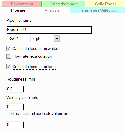
Here you need to specify:
pipeline name - select the name you would like to see in the output documents with calculation results for this pipeline;
flow units - mass or volume. Please note that:
in this field, only the choice between mass and volume units of flow measurement is made. The units of measurement themselves (kg/h, t/h, l/min, etc.) are specified in the project parameters;
when
calculating gas flow, the volumetric flow rate in the initial
data and calculation results is interpreted as the flow rate at metric standard conditions (at
a temperature of 0C and atmospheric pressure), about which a corresponding
note is made opposite the unit of measurement of the flow rate  ;
;
When calculating multiphase flows, as well as when performing heat analysis of liquids, in order to avoid misunderstandings and confusion, it is not allowed to specify volumetric flow rates (since the volumetric flow rate depends on the density of the pumped fluid, and therefore, it can be different at the beginning, middle and end of the same pipe). In these cases, flow rates should be specified only in mass units. In all other cases, both mass and volumetric units of flow measurement can be used.
calculate losses welds where pipes are connected to each other. It has been established empirically that pipelines with welded joints have slightly higher hydraulic resistance compared to similar pipes without welds. Therefore, for a more accurate calculation of friction losses in pipelines, it is recommended to enable this option and take into account the correction for welded joints. This option should be disabled only when calculating pipes that do not have welded joints (for example, plastic pipes connected by flange joints). The number of welds is calculated as one weld for every 6 meters of pipe, plus one weld at the beginning and end of each pipeline element - for example, for a pipe section 20m long, it is assumed that it consists of 4 sections 6m + 6m + 6m + 2m, between which there will be 3 welds, plus 2 welds at the beginning and end of the section - a total of 5 welds;
flow rate recalculation - this option determines the boundary conditions with which the final verification calculation will be performed after selecting the diameters at diameters calculation of the pipeline. The fact is that due to the discreteness of the diameter values (the diameters are selected from a number of standard values), it may turn out that the pipeline with the selected diameters will operate in a mode slightly different from the specified one. Either the flow rates will slightly deviate from the specified ones (if the pressures at the flow consumers are fixed), or the pressures at the consumers will be slightly higher than required (if the fluid flow rates are fixed). Using the "flow rate recalculation" option, the user can specify what to take as fixed in the calculation and what to recalculate. If this option is disabled, the specified fluid flow rates are considered constant (it is assumed that flow control devices will then be installed in the pipeline to maintain the specified flow rates) - in this case, after selecting the diameters, the program will perform a verification calculation of the pipeline with the selected diameters and specified flow rates and determine the final pressures at the consumers. If you enable this option, the specified outlet pressures at consumers will be considered constant, and the flow rates will be recalculated (hence the name of this option) at a verification calculation of the pipeline with the selected diameters. The second option assumes that the flows are not regulated and it is necessary to ensure that the fluid flow rates in the pipeline are not lower than the required values, which in some cases may require increasing the diameters of some pipeline branches. Therefore, in the diameters calculation with the "flow rate recalculation" option enabled, the diameter values are often larger than if this option is disabled. So, in order to avoid an unreasonable increase of the selected pipeline diameters values, it is recommended to enable this option only when necessary - namely, in the case when the pipeline does not assume the installation of flow control devices and it is necessary to ensure that the fluid flow rates to each of the consumers are not lower than the required ones (for example, such conditions are often encountered in the calculations of fire extinguishing pipelines). In cases where the flow rates in the pipeline are planned to be controlled, it is better to disable this option in order to select the most economical pipeline configuration. The "flow rate recalculation" option is used only in the diameters calculation of pipelines; in all other calculations, the presence/absence of this checkbox is ignored;
calculate losses on tees - this option allows you to disable the consideration of the hydraulic resistance of tees when calculating a pipeline, for example, to speed up the calculation or to improve the convergence of calculations of very complex systems with very difficult to calculate hydraulic regimes (which in practice is extremely rare). Since the hydraulic resistance of tees can be very significant in the total resistance of the pipeline, it is not recommended to disable this option unless necessary;
the roughness of the inner surface of the pipe in many cases (but not all) determines the pressure loss due to friction in pipes. It is recommended to take the roughness value according to the data in the table below:
Pipe type and material |
Pipe surface condition and operation conditions |
Roughness, mm |
Weldless brass, copper and lead pipes |
Technically smooth |
0,0015 – 0,0100 |
Aluminum pipes |
Technically smooth |
0,015 – 0,06 |
Weldless steel pipes |
New, unused (depending on time spent in storage) |
0,02 – 0,10 |
Cleaned after many years of operation |
Up to 0,04 |
|
Bitumen-coated |
Up to 0,04 |
|
Steam heat networks with superheated steam and water heat networks with deaeration and chemical cleaning of running water |
0,10 |
|
After one year of operation in gas distribution networks |
0,12 |
|
Gas well tubing after several years of operation under various conditions |
0,04 – 0,20 |
|
Gas well casing after several years of operation under various conditions |
0,06 – 0,22 |
|
Steam networks and water heat networks with insignificant leaks (up to 0.5%) and replenishment deaeration |
0,20 |
|
Water heat networks regardless of source |
0,20 |
|
Oil pipelines for average operation conditions |
0,20 |
|
Moderately corroded |
~0,4 |
|
With small scale deposits |
~0,4 |
|
Steam networks operating intermittently (with downtime) and condensate pipelines with an open condensation system |
0,5 |
|
Air-channels with compressed air using piston and turbo compressors |
0,8 |
|
After several years of operation under various conditions (corroded or with small scale deposits) |
0,15 – 1,0 |
|
Condensate pipelines operating intermittently and water heat networks without deaeration and chemical cleaning of replenishing water with significant leaks (up to 1.5 – 3%) |
1,0 |
|
Water network pipes in operation |
1,2 – 1,5 |
|
With large scale deposits |
~3,0 |
|
In bad condition; with unevenly coated joints |
Over 5,0 |
|
Welded steel pipes |
New or old in excellent conditions; welded or riveted joints |
0,04 – 0,10 |
New bitumen-coated |
~0,05 |
|
Used, partially dissolved bitumen, corroded |
~0,10 |
|
Used, uniform corrosion |
~0,15 |
|
No noticeable irregularities in joints; inside coated with varnish (around 1.00 mm layer); good surface condition |
0,3 – 0,4 |
|
Main gas line after many years of operation |
~0,5 |
|
With single or double transverse riveting; inside coated with varnish (1.00mm layer) or without coating but uncorroded |
0,6 – 0,7 |
|
Inside coated with varnish but not without oxidation; polluted through water operation but uncorroded |
0,95 – 1,0 |
|
Layered deposits, main gas line after 20 years of operation |
1,1 |
|
With double transverse riveting, uncorroded; polluted through water operation |
1,2 – 1,5 |
|
Small scale deposits |
1,5 |
|
With double transverse riveting; significant corrosion |
2,0 |
|
Significant deposits |
2,0 – 4,0 |
|
25 years of operation in city gas network, uneven tar and naphthalene deposits |
2,4 |
|
In bad condition; with unevenly coated joints |
Over 5,0 |
|
Riveted steel pipes |
Single longitudinal and transverse riveting; inside coated with varnish (1.00mm layer); good surface condition |
0,3 – 0,4 |
With double longitudinal and single transverse riveting; inside coated with varnish (1.00mm layer) or without coating but uncorroded |
0,6 – 0,7 |
|
With single transverse and double longitudinal riveting; inside tarred or coated with varnish (1.0 – 2.0mm layer) |
1,2 – 1,3 |
|
With four to six longitudinal rivet rows; long operation time |
2,0 |
|
With four transverse and six longitudinal rivet rows; with evenly coated joints |
4,0 |
|
In bad condition; with unevenly coated joints |
Over 5,0 |
|
Roofing steel |
Drying oil covered |
0,10 – 0,15 |
Not covered by drying oil |
0,02 – 0,04 |
|
Galvanized steel pipes |
Pure galvanization, new |
0,07 – 0,10 |
Regular galvanization |
0,1 – 0,15 |
|
Galvanized using steel sheets |
New |
0,15 |
Used |
0,18 |
|
Cast iron pipes |
New |
0,25 – 1,0 |
New, bitumen-coated |
0,10 – 0,15 |
|
Asphalt-paved |
0,12 – 0,30 |
|
Water networks, used |
1,4 |
|
Used, corroded |
1,0 – 1,5 |
|
With deposits |
1,0 – 1,5 |
|
With significant deposits |
2,0 – 4,0 |
|
Cleaned after many years of operation |
0,3 – 1,5 |
|
Significantly corroded |
Up to 3,0 |
|
Concrete pipes |
Good surface with smoothing |
0,3 – 0,8 |
Average conditions |
2,5 |
|
Rough |
3 – 9 |
|
Reinforced concrete pipes |
|
2,5 |
Asbestos-cement pipes |
New |
0,05 – 0,10 |
Average |
~0,60 |
|
Cement pipes |
Smoothed |
0,3 – 0,8 |
Untreated |
1,0 – 2,0 |
|
Mortar not smooth over joints |
1,9 – 6,4 |
|
Glass pipes |
Pure glass |
0,0015 – 0,010 |
velocity up to, - depending on the calculation type, this parameter is taken into account differently. When performing a pipeline diameters calculation, they are selected in such a way as not only to ensure the specified fluid flow rates in the pipeline for a given pressure difference (between the pressure at the initial and final points), but also to ensure that the fluid velocity do not exceed the maximum allowable value specified in this field. When performing other types of calculations, the velocity limit can be left blank since it performs only a diagnostic function - if at any point in the pipeline the fluid velocity exceeds value specified in this field, the program shows a corresponding message in the calculation log. Recommended values of velocity for various gas and liquid fluids in process piping, as well as oil and petroleum products are given in the tables below:
Recommended velocities of gases and vapors in process piping
Fluid |
Pressure (abs.), MPa |
Velocity, m/s |
||
Steam |
Dry saturated |
NS <= 200 |
|
35 |
NS > 200 |
|
60 |
||
Superheated |
NS <= 200 |
|
50 |
|
NS > 200 |
|
80 |
||
Exhausted |
|
10 – 15 |
||
Hydrogen |
|
15 |
||
Oxygen |
Up to 1,6 |
30 |
||
1,6 – 4 |
16 |
|||
4 – 10 |
6 |
|||
10 – 25 |
3 |
|||
Hydrocarbon vapors |
0,005 – 0,02 |
60 – 75 |
||
0,02 – 0,05 |
40 – 60 |
|||
0,05 – 0,1 |
20 – 40 |
|||
0,1 and higher |
10 – 25 |
|||
Coolants |
Propane, propylene, ethane, ethylene, ammonia |
Up to 2,0 |
10 – 25 |
|
Freons |
8 – 18 |
|||
Other gases and vapors |
Up to 0,3 |
5 – 20 |
||
0,3 – 0,6 |
10 – 30 |
|||
0,6 – 10 |
10 – 35 |
|||
10 and higher |
40 |
|||
Recommended velocities of liquids in process piping
Fluid |
Kinematic viscosity, cSt |
Velocity in suction pipelines, m/s |
Velocity in discharge pipelines, m/s |
|
Liquid coolants, ethylene glycol and saline solutions |
NS <= 200 |
|
0,6 |
1,2 |
NS > 200 |
|
1,0 |
2,0 |
|
Liquefied gases |
|
1,2 |
3,0 |
|
Liquid at boiling temperature and hot water |
|
0,9 |
0,9 |
|
Other liquids |
Up to 11 |
1,5 |
2,5 |
|
11 – 28 |
1,3 |
2,0 |
||
28 – 74 |
1,2 |
1,5 |
||
74 – 148 |
1,0 |
1,2 |
||
148 – 445 |
1,0 |
1,1 |
||
445 and higher |
0,8 |
1,0 |
||
Recommended velocities of oil and petroleum products in pipelines
Diameter, mm |
Velocity, m/s |
< 250 |
1.0 |
300-350 |
1,1 |
400 |
1,2 |
500 |
1.3 |
600 |
1.4 |
700 |
1.6 |
800 |
1.9 |
900 |
2.1 |
1000 |
2,3 |
1200 |
2.7 |
In addition, the user can define his own value of the fluid velocity limit if there are any special considerations regarding velocity limitation for the pipeline being calculated (e.g. preventing the formation of static charge on the pipe surface due to friction of a viscous product, preventing noise, etc.).
first branch start node elevation - here you need to specify the "zero mark" for plotting the piezometric chart, relative to which the curves on the graphs on this chart will be plotted. If you do not need to form a piezometric graph, you can leave this parameter blank. In addition, the program can automatically calculate the height of the starting point of the first branch, if you specify the elevation height of any other pipeline node. For more information on how to do this, see Working with pipeline nodes .