Working with pipeline nodes
To view and set the parameters of pipeline nodes, you need to select the node of interest on the graphic window (or in some of the list windows), after which its characteristics will be displayed in the Object Properties Window:
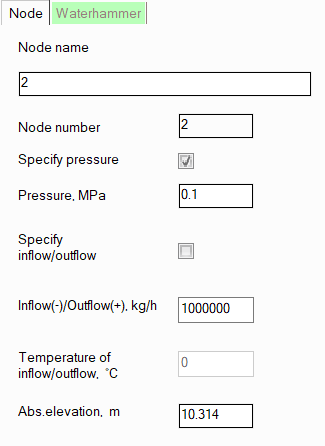
node name - by default, the node name is the same as its number, but if necessary, you can assign any name to the node here, which will be displayed for it on the pipeline diagram;
pressure in the node - depending on the hydraulic calculation task being solved, the pressure value in a node can be either known - in this case it is specified, or an unknown sought value - in this case it is not specified (for more details, see boundary conditions of hydraulic calculation). Please note that pressures in intermediate pipeline nodes are usually not specified. Incorrect specifying of pressure in an intermediate node can lead to an incorrect calculation task formalization, since the entered pressure value will be considered a boundary condition for hydraulic calculation. This can lead to a recalculation of fluid flow rates in the branches associated with this node.
inflow/outflow in a node - instead of assigning the flow rate for branches, you can assign the fluid inflow/outflow values in the branch nodes. If the node is terminal (i.e., the initial or final node of the pipeline system), then entering the inflow/outflow in this node is equivalent to entering the flow rate in the branch starting/ending in this node (you can assign either the flow rate in the branch or the inflow/outflow in the node - whichever is more convenient to you). Please note, that in this case for an inlet node the inflow (negative value) should be specified, while for an outlet - the outflow (positive value). If the node is intermediate, then assigning the inflow/outflow in such a node can be used to simulate the removal of a portion of the fluid from the pipeline (i.e., the outflow - with the "+" sign) or, conversely, its supply to the pipeline "from the outside" (the inflow - with the "-" sign). Similar to the fluid flow rate in a branch, the inflow/outflow values in nodes, depending on the hydraulic calculation task being solved, can be either known - in this case they are specified, or unknown - in this case they are left unspecified (for more information, see the boundary conditions of hydraulic calculation). If the "Specify inflow/outflow" checkbox is not checked, then for this node, the Inflow/Outflow field will display the inflow/outflow value calculated based on the balance of fluid flow rates specified in the branches related to this node. Please note that:
non-zero inflows/outflows are not allowed for nodes with tees;
it is not allowed to specify inflows/outflows in nodes when calculating multiphase flows - in this case, fluid flow rates should be specified by branches.
temperature of inflow/outflow - when specifying the inflow of the fluid in the node, its temperature must also be specified. This temperature may differ from the temperature of the flow entering this node from other branches, which will be taken into account in the heat calculation of the pipeline;
absolute elevations of nodes - these fields display the absolute heights of nodes automatically calculated by the program. The calculation is performed as follows: the starting point of the first pipeline branch is taken as a certain "zero mark" (with an absolute elevation of 0 m) and then, based on the entered data on the geometry (elevation differences) of the elements of this branch, the elevation mark of the end node of the branch is calculated, and similarly, the elevation marks of all other nodes of the pipeline are calculated for further branches. If necessary, you can specify your own zero mark in this field - the heights of the other nodes will be recalculated relative to the entered value automatically.
Please note that node parameters can also be set by selecting any of the branches to which the node belongs and opening the "Nodes" tab for it in the Object Properties Window - for more information, see Setting branch node parameters.
To insert nodes into an already modeled
pipeline, click the  button of the Edit toolbar
(or use the Insert - Node menu
item), then left-click on the pipe section or other pipeline element where
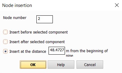
you want to insert the node. A window will appear in which you will need
to specify the number of the new node (the first free one is suggested
by default) and the position of the new node relative to the selected
component:
button of the Edit toolbar
(or use the Insert - Node menu
item), then left-click on the pipe section or other pipeline element where
you want to insert the node. A window will appear in which you will need
to specify the number of the new node (the first free one is suggested
by default) and the position of the new node relative to the selected
component:
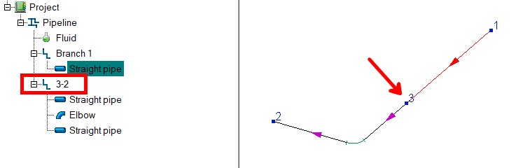
When inserting a node into a branch, this branch is "cut" into two separate branches. For example, if node 3 is inserted into a branch with a start node 1 and an end node 2, then as a result the first branch (with the original name) will start at node 1 and end at node 3 (and this branch will only contain elements located at the beginning of the original branch before the "cut point"). And another branch will be added to the project tree, following from node 3 to node 2 (the default name of this branch will be "3-2", but it can be changed if necessary), in which all the pipeline elements "cut off" from the first branch will be:
The node insertion operation may
be required to add some "forgotten" pipe branching, as well
as to add some pipe element to the middle of the pipe. If necessary, the
node insertion operation can be cancelled using the  button of Edit toolbar
or the corresponding Edit menu
command.
button of Edit toolbar
or the corresponding Edit menu
command.
Intermediate pipeline nodes, where
one branch ends and one begins, can be deleted from the pipeline. To do
this, select the node and click the  button of
the Edit toolbar or use
the corresponding Edit menu item
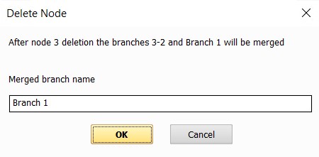
(or simply press the Delete key on the keyboard). When deleting a node,
the two branches that connect at the node are combined into one. In the
window that appears, enter the name of this "combined" branch
(the name of the first of the branches to be combined is suggested by
default):
button of
the Edit toolbar or use
the corresponding Edit menu item
(or simply press the Delete key on the keyboard). When deleting a node,
the two branches that connect at the node are combined into one. In the
window that appears, enter the name of this "combined" branch
(the name of the first of the branches to be combined is suggested by
default):
Note that:
you can only delete nodes where two branches are connected. It is not possible to delete the start/end node of a pipeline or the merge/split nodes of flows (where 3 or more branches are connected);
it is impossible to delete a node that connects
branches with different directions (i.e., if this node is either the
initial node for both branches, or the final node). To delete such
a node, you must first change the direction of one of these branches
using the  button of
the Edit toolbar,
the Edit menu, or the corresponding
context menu command (called by right-clicking on the branch in the
project tree);
button of
the Edit toolbar,
the Edit menu, or the corresponding
context menu command (called by right-clicking on the branch in the
project tree);
you need to be careful when deleting nodes with non-zero fluid inflows/outflows - when you delete a node, the inflow/outflow will be deleted along with it;
care must be taken when deleting nodes connecting branches with different fluid temperatures, flow rates, mass gas contents and/or fluids - in this case, for the "combined" branch the temperature/flow rate/mass gas content/fluid of the first (in the direction of flow) of the branches being combined will be used;
when deleting nodes connecting branches with different diameters, a reducers from one diameter to another with an unspecified length will be automatically added at the location of the deleted node.
If necessary, the node insertion
operation can be cancelled using the button of
Edit toolbar or the corresponding Edit
menu command.