 of Components
toolbar
(or use the appropriate item in the
"Insert"
menu). If the selected node already contains a tee, it must be removed
first.
of Components
toolbar
(or use the appropriate item in the
"Insert"
menu). If the selected node already contains a tee, it must be removed
first.Tee
To add a tee, select
the node into which you want to insert the tee on the Graphic window or
in the Data List Window (by enabling the Node view in the drop-down list
at the top of this window) and click the button of Components
toolbar
(or use the appropriate item in the
"Insert"
menu). If the selected node already contains a tee, it must be removed
first.
The tee element is used to model hydraulic resistance that occur when flows merge/split in tees/olets. This hydraulic losses are caused by the changes in fluid flow rates before/after merging/separating, turning the flow, etc. It is important to understand that the way in which flows merge/split does not have a fundamental effect on this hydraulic resistance. Therefore, regardless of how exactly the pipes are connected - by a tee or, for example, by welding one pipe into another - the tee element can be used to model this resistance in both cases.
Unlike all other piping components, a tee is added as a set of three separate elements - tee niches (or legs). After inserting a tee, each of its three niches will be added to the corresponding pipeline branch and their characteristics will be displayed in the Object Properties Window:
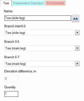
name - by default, all tee niches are assigned standard names depending on their types ("Tee (main leg)" or "Tee (side leg)"). However, if necessary, these names can be changed in this field. When switching between different types of tee legs, their names will also change to the corresponding ones. If you manually change the name of one of the tee legs, it will become the same for all legs of this tee. Specify the name that you would like to see for this element in reports with calculation results. To display the name of this tee niche on the diagram, click the corresponding button to the right of the name. If you need to enable displaying the name of another tee niche on the diagram, select the corresponding tee niche on the diagram or in the project tree and click the corresponding button to the right of the name in the Object Properties window for it;
tee niche type - here for each of the tee niches related to the corresponding pipeline branch, you can change its type ("Tee (main leg)" or "Tee (side leg)"). The names of the branches are signed above the corresponding tee type switch.
This version of the program considers only those tees in which the side leg is strictly perpendicular to the main ones:
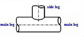
Accordingly, the tee must have only one side leg and two main legs. If the tee is inserted into a node in which three branches are connected, for each of which their pipes (and other components) have already been specified, then by the spatial orientation of the pipes adjacent to the node with the tee, it is easy to understand in which branch what type of tee niche (main or side leg) will be. Therefore, in this case, when inserting the tee, the program will automatically assign the correct types to each of the tee niches. However, if you insert a tee into an "unfinished" branching (for example, if not all three branches connecting in this node have been specified or not for all of them their pipes and other components have been specified), then since in this case the directions of the tee niches are not clearly defined, when inserting the tee the program may "misguess" the directions of the niches and assign them incorrect types. In this case, the types of tee niches can then be switched manually in the corresponding drop-down lists. However, for convenience, it is recommended to specify tees last, when all other elements of the branches adjacent to a given tee have already been specified and the types of the tee niches are determined unambiguously.
It also should be noted that this version of the program considers only those tees in which the diameters of the main legs are equal to each other and the diameter of the side leg is less than or equal to the diameter of the main legs. Therefore:
if modeling a tee in which the diameter of the side leg turns out to be larger than the diameters of the main legs, the values of the main legs diameters are automatically recalculated at the calculation and become equal to the diameter of the side leg;
if modeling a tee in which one of the main leg has a larger diameter than the other, at the calculation the diameter of the smaller main leg is automatically recalculated and becomes equal to the diameter of the larger main leg.
In each of the specified cases, when calculating the hydraulic resistance of the tee, the program takes into account, in addition to the resistance of the tee itself, also the hydraulic resistance of the diameter change from the diameter specified by the user to the diameter determined during this conversion.
quantity - this parameter is usually not used for tees. It is used for other pipeline elements (for example, for valves) when modeling several identical elements. In this case, you can enter the number of these elements in this field and at the calculation the hydraulic resistance and heat losses on this element will be multiplied by the specified value. Since there are unlikely to be several identical tees in one pipeline branch, this option is of no practical interest for it.
Please note that from a hydraulic point of view, tees are considered as "point" (or "concentrated") resistances that have no lengths. Therefore, if it is necessary to take into account the dimensions of the tee niches in the calculation (to calculate and account for the friction losses, heat losses and hydrostatic pressure drop that occur on them), they can be modeled separately as pieces of pipes with the corresponding lengths, or their lengths can be added to the lengths of the pipes adjacent to the corresponding tee niches. However, this only makes sense in cases where:
the tee niches have really large sizes that cannot be neglected;
one or all of the niches of the tee are located in a vertical or inclined plane relative to the vertical - in this case, it is important to take into account the hydrostatic pressure differences that occur on them;
one or all of the niches of the tee are located in a closed loop (so that the piping model looks correctly, without gaps).
In other cases, losses in the tee niches (and therefore their lengths) are usually neglected.