Pipeline
branches
To add a new branch, select a pipeline
(or any already existing branch) in the project tree and click the  button of the Components
toolbar (or use the corresponding Insert
menu item) - the new branch will be added to the project tree after the
selected element. It is important to remember that the order of branches
in the project tree is not essential for calculating the pipeline. Therefore,
branches can be added to the pipeline in any order; if they were inserted
in the wrong order, they can be swapped at any time using the standard
Cut/Paste commands of the Edit toolbar, the Edit
menu, or the context menu (called by right-clicking on a branch in the
project tree) - for more information, see here.
button of the Components
toolbar (or use the corresponding Insert
menu item) - the new branch will be added to the project tree after the
selected element. It is important to remember that the order of branches
in the project tree is not essential for calculating the pipeline. Therefore,
branches can be added to the pipeline in any order; if they were inserted
in the wrong order, they can be swapped at any time using the standard
Cut/Paste commands of the Edit toolbar, the Edit
menu, or the context menu (called by right-clicking on a branch in the
project tree) - for more information, see here.
In
addition, a branch can be added by activating one of the pipeline nodes
in the diagram - in this case, this node will be considered the default
starting node of this branch.
After
adding a branch, a list of its initial data will be displayed in the Object
Properties Window:
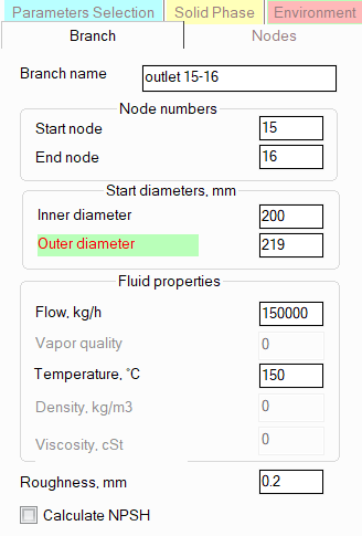
branch name - specify the
name for each branch that you would like to see in the reports with
the calculation results for this pipeline;
start and
end node numbers - please note that only integer values
(letters and other symbols are not allowed) with no more than 8 characters
can be used as node numbers (the program does not currently support
9-digit or more node numbers) and it is necessary to ensure that node
numbers are unique -
so that the same node number is not used for two or more different
points in the pipeline. The start and end node numbers determine the
direction of the branch, however, the flow direction in this branch
may be the opposite - see below for more information. To quickly change
the direction of a branch, use the "Reverse direction" command
in the context menu called by right-clicking on the branch in the
project tree or the similar button in the Edit
toolbar, or use the corresponding item in the Edit
menu;
start diameters -
here you need to specify the "initial" diameters, i. e.
the diameters of components at the beginning of a given branch before
its first change (for example, at a reducer or other element with
a change in diameters). If there are no elements with a change in
diameter in a branch, then all elements of the branch will have diameters
equal to the "initial" ones. Depending on the type of calculation,
diameters can be specified in the initial data or be unspecified:
When
performing diameters calculation
of a pipeline, the diameters are unknown, so they are usually
not specified in the initial data (they are left equal to zero).
However, for some branches, the diameters may be known - for example,
if part of the calculated pipeline model has already been designed
(or even built) and it is necessary to determine the diameters
only for the rest of the pipeline system. In this case, the known
diameters of the branches are specified in the initial data, and
for branches with unknown diameters, they are left unspecified.
In branches with unspecified diameters, reducers and other piping
components with a change in diameter are not allowed.
When
performing an
isothermal flow analysis, it is sufficient
to specify only the value of the inner diameter; diameters must
be specified in all branches.
When performing heat analysis and waterhammer calculations,
both the inner and outer diameters must be specified for each
branch of the pipeline.
Please note that when changing the
specified branch diameters, the
program will not only automatically adjust the values of the diameters
of the components of this branch (up to the first element with a change
in diameter if any), but will also change the values of the
radii of the bends and elbows in this branch if they are equal to the
standard value of 1.5*DN (for pipes with DN < 500mm) or 1*DN (for
pipes with DN >= 500mm).
fluid flow
rate - depending on the hydraulic calculation task being
solved, the flow rate value can be either known - in this case it
is specified, or an unknown sought value - in this case it is not
specified (for more details, see boundary conditions of hydraulic
calculation). For branches with unknown flow rates, it
is allowed to specify approximate flow rate values as an "initial
approximation" in the calculation, however, the entered values
must not 'conflict' with the flow rate values in neighboring branches
(therefore, if there are doubts about the flow rate values in such
branches, it is better not to specify them at all than to specify
incorrect values). Please note that the flow direction in a branch
may not coincide with the direction of the branch itself. For example,
if the branch has an initial node 1, the end node 2 (that is, the
branch is directed from the 1st node to the 2nd), and the flow must
be directed vice versa, from node 2 to node 1, it is necessary to
specify a negative value of a flow rate for the branch. Similarly,
if in the calculation results for any branch/branches the fluid flow
rate appeared to be negative, this means that the flow in this branch
goes in the direction opposite to the direction of the branch.
A
special case is the assignment of flow rates for "three-phase"
mixtures (of oil, water and natural gas). If three fluids are specified
in the project tree, then the flow rates of each of the three phases (oil,
water and gas) must be specified separately by clicking the corresponding
button opposite the flow rate in the Object Properties Window for the
branch:
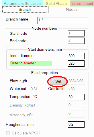
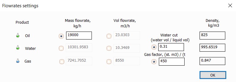
The
flow rates can be specified either explicitly (in kg/hour, m3/hour and
other units) for each of the phases, or in the form of oil flow rate (it
is mandatory) and water cut and gas factor coefficients (or any combinations
of these values with each other):
vapor quality (a.k.a. mass gas content) -
this parameter is the mass flowrate fraction of gas in the gas-liquid
flow, and is used only when calculating gas-liquid flows. Its value
can lie in the range from 0 to 1. When the gas content = 0, the flow
consists entirely of liquid (the gas fraction is 0); when the gas
content = 1, the flow consists entirely of gas; when the vapor quality
values between 0 and 1, the flow is in the vapor-liquid state. The
vapor quality should be specified for all source branches (the initial
nodes of which are source nodes for the pipeline system). For other
pipeline branches, the gas content can be omitted; it will be determined
by calculating the previous (in the direction of flow) pipeline branches.
Depending on the selected model
for calculating two-phase flows, the value of this
parameter will be interpreted in the calculation differently:
when
calculating a flow taking
into account flashing/condensation of the fluid
(when the "Undefined" phase state of the fluid is specified),
the entered value of the vapor quality is interpreted as the fraction
of gas at
the initial point of the flow. And its further change along
the pipeline, caused by boiling/condensation of the fluid, is
determined during the calculation. In addition, when specifying
the "Undefined" fluid phase state, it is allowed not
to specify the value of the vapor quality if the pressure and
temperature of the flow are specified for this initial point of
the pipeline. In this case, the gas content will be determined
in the phase equilibrium calculation for the specified pressure
and temperature. However, it is important to remember that for a single-component fluid, only
a single-phase state (liquid or gas) can be modeled in this way,
since boiling/condensation of a single-component fluid occurs
at a constant temperature if the pressure is fixed, and vice versa
- if the temperature is fixed, then at a constant pressure. That
is, any gas fraction from 0 to 1 can correspond to each pair of
pressure and temperature values. Therefore, if a single-component
fluid is in a vapor-liquid state at the starting point of the
pipeline, its vapor quality (gas content) must be specified.
when
calculating a "frozen"
two-phase flow (when two fluids are specified in the project tree,
describing the parameters of the liquid and gas phases separately),
the entered value of the gas content is considered constant throughout the entire
branch. In subsequent branches, the gas content may change
(for example, when mixing two flows with different gas contents),
which is calculated by the program automatically. Since in the
case of a "frozen" flow, the effects of boiling/condensation
of the fluid along the pipeline are not taken into account and
the phase equilibrium is not calculated, the gas content must
be specified in all source branches (it is impossible to determine
it by pressure and temperature as in the case of a flow with boiling/condensation
described above).
If
you are unsure of what type of calculation you will be performing for
a pipeline, just in case, set the temperatures in all branches.
Please
note that when calculating two-phase flows using the model taking into
account boiling/condensation of the fluid along the pipeline (when the
"Undefined" fluid phase state is specified), it is permissible
not to specify the temperature in the source branch if the vapor quality
value for this branch is specified greater than 0 but less than 1. In
this case, the flow temperature will be automatically determined by calculating
the phase equilibrium for the specified gas content and pressure at the
starting point. If both the temperature and the gas content (greater than
0 but less than 1) are specified for the branch, then it is considered
that the gas content value has a higher priority, so the flow temperature
in this case will be recalculated when calculating the phase equilibrium
for the specified pressure and gas content.
A special case is pipelines with
an "Undefined" fluid phase state, consisting of one branch,
in which the pressure at the end node is specified. For such pipelines,
the specified values of the mass gas content and/or temperature in the
branch are interpreted as the gas content/temperature of the flow at the end point of the pipeline,
and an "inverse" heat and hydraulic calculation is performed
for them in order to determine the required pressure, temperature and
gas content of the flow at the inlet of the pipeline. Such a hydraulic
analysis calculation task is, in particular, quite often used in the calculation
of "transfer" pipelines feeding oil in a vapor-liquid state
from furnaces/heaters to a distillation column.
density
and viscosity of the fluid
- are set only in the case when manual input of properties is
used for the liquid product, but the table of fluid properties vs.
temperature is not specified. In this case, the fluid properties (density
and viscosity) are set separately for each pipeline branch;
roughness
of the inner surface of the pipe - initially this parameter
is set for the
pipeline, therefore by default the same roughness value
will be set for the branch and used in the calculation as in the pipeline
to which this branch belongs. However, if necessary, different roughness
values can be set for different branches of the pipeline (for example,
if part of the pipeline is "old", part is "new"
or if the pipeline is partially made of steel pipes, partially of
plastic pipes, etc.).
calculate NPSH -
by default, the calculation of NPSH in the pipeline is not performed
(since it's usually not of a great interest for the major part of
any piping system), therefore the user must "mark" those
branches for which it is necessary to calculate the NPSH by enabling
this option for these branches.
Setting
branch nodes parameters
The
branch node data is specified in the Nodes tab of the Branch Properties
Window; these include:
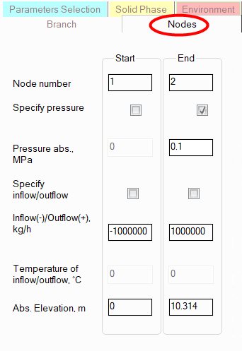
pressure
in nodes - depending on the hydraulic calculation task
being solved, the pressure value in a node can be either known - in
this case it is specified, or an unknown sought value - in this case
it is not specified (for more details, see boundary conditions of hydraulic
calculation). Please note that pressures in intermediate
pipeline nodes are usually not specified. Incorrect specifying of
pressure in an intermediate node can lead to an incorrect calculation
task formalization, since the entered pressure value will be considered
a boundary condition for hydraulic calculation. This can lead to a
recalculation of fluid flow rates in the branches associated with
this node.
inflow/outflow
in a node - instead of assigning the flow rate on the
"Branch" tab, you can assign the fluid inflow/outflow values
in the branch nodes. If the node is terminal (i.e., the initial or
final node of the pipeline system), then entering the inflow/outflow
in this node is equivalent to entering the flow rate in the branch
starting/ending in this node (you can assign either the flow rate
in the branch or the inflow/outflow in the node - whichever is more
convenient to you). Please note, that in this case for an inlet
node the inflow
(negative value) should be specified, while for an outlet
- the outflow (positive
value). If the node is intermediate, then assigning the inflow/outflow
in such a node can be used to simulate the removal of a portion of
the fluid from the pipeline (i.e., the outflow - with the "+"
sign) or, conversely, its supply to the pipeline "from the outside"
(the inflow - with the "-" sign). Similar to the fluid flow
rate in a branch, the inflow/outflow values in nodes, depending on
the hydraulic calculation task being solved, can be either known -
in this case they are specified, or unknown - in this case they are
left unspecified (for more information, see the boundary conditions of hydraulic
calculation). If the "Specify inflow/outflow"
checkbox is not checked, then for this node, the Inflow/Outflow field
will display the inflow/outflow value calculated based on the balance
of fluid flow rates specified in the branches related to this node.
Please note that:
non-zero
inflows/outflows are not allowed for nodes with tees;
it
is not allowed to specify inflows/outflows in nodes when calculating
multiphase flows - in this case, fluid flow rates should be specified
by branches.
temperature of inflow/outflow -
when specifying the inflow of the fluid in the node, its temperature
must also be specified. This temperature may differ from the temperature
of the flow entering this node from other branches, which will be
taken into account in the heat calculation of the pipeline;
absolute
elevations of nodes - these fields display the absolute
heights of nodes automatically calculated by the program. The calculation
is performed as follows: the starting point of the first pipeline
branch is taken as a certain "zero mark" (with an absolute
elevation of 0 m) and then, based on the entered data on the geometry
(elevation differences) of the elements of this branch, the elevation
mark of the end node of the branch is calculated, and similarly, the
elevation marks of all other nodes of the pipeline are calculated
for further branches. If necessary, you can specify your own zero
mark, or make any other height of any node of the pipeline the starting
point. To do this, select the corresponding node of the pipeline (for
more details, see here)
and set the desired absolute elevation value for it - the heights
of the other nodes will be recalculated relative to the entered value
automatically.
Please note
that node parameters can also be set by directly selecting the required
node of the pipeline - for more details, see Working with pipeline nodes.