Modeling of the piping system
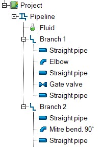
Since the Hydrosystem is a fluid flow analysis program, when modeling a pipeline in the program, it is necessary to model not only the piping system 'itself' (as a sequence of pipes, bends, fittings and other elements), but also to specify the flow 'route' in this pipeline. In Hydrosystem, this is done as follows: the pipeline in the Hydrosystem is made as a sequence of so-called separate branches, the branches in turn consist of piping components (hydraulic resistances) - straight pipes, bends, valves, etc.:
A branch is an unbranched fragment of a pipeline with a constant mass flow rate of the fluid. Each branch connects two pipeline nodes. All pipeline nodes have individual numbers; the direction of each branch is determined by specifying the number of its initial and final nodes. Nodes can be of the following types:
source (inlet) nodes - starting points of a pipeline where only one branch begins;
consumer (outlet) nodes - end points of a pipeline where only one branch ends;
intermediate sources and consumers - nodes where one branch ends and one begins. In this case, the flowrates in these two branches can be either the same (in this case, the node is a "pass-through" node: there will be no fluid inflow/outflow - as much fluid as came into the node from one branch, the same amount will go out to the next branch) or different (in this case, there will be an inflow or outflow of fluid in this node);
flow splitting nodes - nodes where one branch ends and several others begin;
flow merging nodes - nodes where several branches end and one begins;
merging-splitting nodes of flows - nodes where several branches end and several begin.
For example, in the diagram below, there are two source nodes (1 and 2), three consumer nodes (5, 8, and 9), one merging node (3), two splitting nodes (4 and 6), and one intermediate node (7).
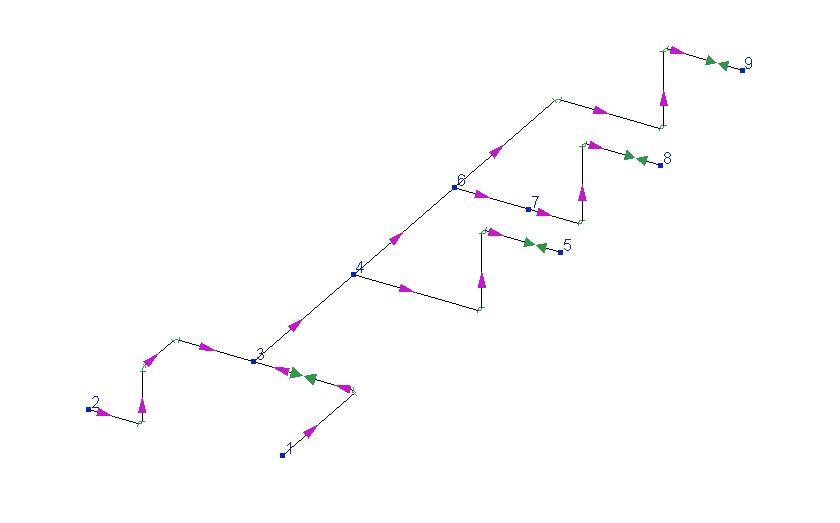
To model such a pipeline system in Hydrosystem, you need to add the following branches to the pipeline:
| Branch | Starting node | End node |
Branch A |
1 |
3 |
Branch B |
2 |
3 |
Branch C |
3 |
4 |
Branch D |
4 |
5 |
Branch E |
4 |
6 |
Branch F |
6 |
7 |
Branch G |
7 |
8 |
Branch H |
6 |
9 |
after which it is necessary to add to each of these branches their components, i.e., hydraulic resistances (pipes, bends, fittings, etc.).
Please note that the order of branches following each other is not essential for pipeline calculations (since the direction and flow pattern in the pipeline is determined not by the order of branches, but by the numbers of their initial and final nodes), while the resistances in the branch must be specified in the order in which they follow in the real pipeline. When modeling schemes, you can use group operations with elements of the pipeline system (branches, components, etc.) - copying/pasting/deleting pipeline fragments and group replacement of their parameters.
If there is no fluid inflow/outflow at node 7 (that is, if the flow rates in Branches F and G are the same), then this node can be removed without changing the topology of the pipeline, thereby merging Branches F and G into one branch.