Additional pipeline calculation settings
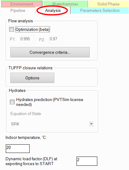
On the "Analysis" tab of the Object Properties Window for a pipeline, you can also specify some "fine" calculation settings and additional options that may be required in certain rare cases.
These include:
Optimization of flow distribution calculation in complex piping models - this option is used for calculations of complex piping systems with a large number of branches, in which there are disproportionate fluid flowrates (when the flows in some branches are hundreds or thousands of times less than in others). Using this option in some cases allows for better convergence of calculations for such pipelines.
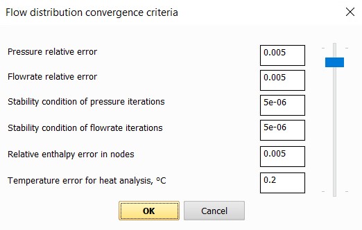
Convergence criteria – this option allows you to set the allowable relative errors (by pressure, flow rate, etc.) of the calculation. Errors can be either set manually for each parameter or changed synchronously for all parameters by moving the corresponding "slider" up and down (the most accurate calculation with the smallest errors is at the top, the maximum errors are at the bottom). Increasing the errors allows to achieve better convergence of pipeline calculations with high flow rates and velocities, as well as with disproportionate flow rates in different branches (for example, when the flow rates on some branches of the pipeline are several orders of magnitude lower than on others).
TUFFP closing relations - this option allows more flexible configuration of the so-called "closing relations" for hydraulic calculation of two-phase flow using the "Unified model" method of the TUFFP project. The "closing relations" include methods for calculating certain parameters of a two-phase flow: the interfacial friction factor, slug holdup and entrainment in slug flow, drift velocity, etc.:
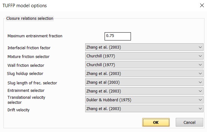
By default, the wetted surface and the shape of the interphase surface in stratified flow are calculated according to [3], the true volumetric contents of the phases in slug flow and the parameters of liquid entrainment by gas according to [1-2], the length of the slugs in slug flow according to [5-6], the coefficient of interphase friction according to [4]. The universal Churchill equation [7] is used to calculate the coefficient of hydraulic friction.
Please note that to use the "Unified model" it is necessary to select the "TUFFP Method" when specifying the two-phase flow analysis methods. The methods used in the calculations according to the "Unified model" are described in more detail in [8-12].
Hydrate prediction - this option allows you to calculate hydrate precipitation along the pipeline using a special thermodynamic package PVTSim manufactured by Calsep. To use this option, the PVTSim package must be installed on this computer and a license for it must be available. Hydrate precipitation calculation methods are described in detail in the PVTSim documentation.
Indoor temperature - this parameter is used as an environment temperature at heat calculation of indoors piping systems.
Dynamic load factor (DLF) at exporting forces to START-Prof - this coefficient is used when calculating forces induced by waterhammer and gas-liquid slug flow, the values of which are exported to the START-Prof program for stress analysis of the pipeline. It allows taking into account that when dynamic loads (caused by waterhammer or slug flow) are applied to the pipeline system, the deformations of the structure may be 1.0-2.0 times greater than the deformations from static loads. Since the calculation in START-Prof for loads from slug flow and waterhammer is performed by the static method, it is recommended to enter the worst value of the dynamic load factor DLF=2.0 to take into account the dynamic nature of the load. The forces calculated by the program will be multiplied by the DLF coefficient, and the obtained values will be transferred to START-Prof.
References
1. Hong-Quan Zhang, Qian Wang, Cem Sarica, James P. Brill. Unified Model for Gas-Liquid Pipe Flow via Slug Dynamics – Part 1: Model Development. Trans. of ASME, 2003, Vol. 125, pp. 266-273.
2. Hong-Quan Zhang, Qian Wang, James P. Brill. A Unified Mechanistic Model for Slug Liquid Holdup and Transition between Slug and Disperse Bubble Flows. Int. J. Multiphase Flow, Vol. 29, pp. 97-107.
3. Hong-Quan Zhang, Cem Sarica. A Model of Wetted-Wall Fraction and Gravity Center of Liquid Film in Gas/Liquid Pipe Flow. SPE Journal, 2011, Vol. 16, N 3, pp. 692-697.
4. Cohen L.S., Hanratty T.J. Effect of Waves at a Gas-Liquid Interface on a Turbulent Air Flow. J. Fluid Mech. 1968, Vol. 31, N 3, pp. 467-479.
5. Taitel Y., Barnea D., Dukler A.E. Modeling Flow Pattern Transitions for Steady Upward Gas-Liquid Flow in Vertical Tubes. AIChE Journal. 1981, Vol. 26, N 3, pp. 345-354.
6. Barnea D., Brauner N. Holdup of the Liquid Slug in Two-Phase Intermitted Flow. Int. J. Multiphase Flow. 1985, Vol. 11, N 1, pp. 43-49.
7. Churchill S.W. Friction Factor Equations Spans all Fluid-Flow Regimes.Chem. Eng. 1977, Vol. 7, pp. 91-92.91. Bendiksen, K., Malnes, D., Moe, R., N
8. Hong-Quan Zhang, Qian Wang, Cem Sarica, James P. Brill. Unified Model for Gas-Liquid Pipe Flow via Slug Dynamics – Part 1: Model Development. Trans. of ASME, 2003, Vol. 125, pp. 266-273.
9. Hong-Quan Zhang, Qian Wang, Cem Sarica, James P. Brill. Unified Model for Gas-Liquid Pipe Flow via Slug Dynamics – Part 2: Model Validation. Trans. of ASME, 2003, Vol. 125, pp. 274-283.
10. Hong-Quan Zhang, Qian Wang, James P. Brill. A Unified Mechanistic Model for Slug Liquid Holdup and Transition between Slug and Disperse Bubble Flows. Int. J. Multiphase Flow, Vol. 29, pp. 97-107.
11. Hong-Quan Zhang, Cem Sarica. A Model of Wetted-Wall Fraction and Gravity Center of Liquid Film in Gas/Liquid Pipe Flow. SPE Journal, 2011, Vol. 16, N 3, pp. 692-697.
12. Cohen L.S., Hanratty T.J. Effect of Waves at a Gas-Liquid Interface on a Turbulent Air Flow. J. Fluid Mech. 1968, Vol. 31, N 3, pp. 467-479.