
Guide supports permit axial movement along the pipe while restricting lateral displacement. Unlike simple supports, they include stops that prevent horizontal movement perpendicular to the pipe axis. Single-directional guides restrict downward movement but disengage during upward displacement. Double-acting guides remain engaged in both directions. Friction forces during sliding provide resistance to longitudinal movement.


See Global and Local Coordinate Systems
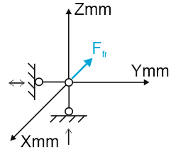
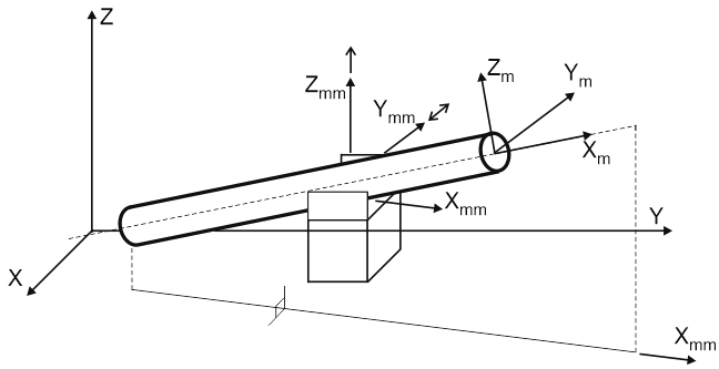
Single-directional guide supports allow axial pipe movement while preventing horizontal displacement. They restrict downward movement but permit upward travel.
PASS/START-PROF models these supports with two linear restraints: a vertical single-directional restraint and a horizontal double-acting restraint, plus axial friction.
Install on pipes inclined up to 18 degrees from horizontal. Sliding surfaces are always horizontal. For inclined surfaces, use custom restraints.
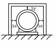
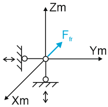
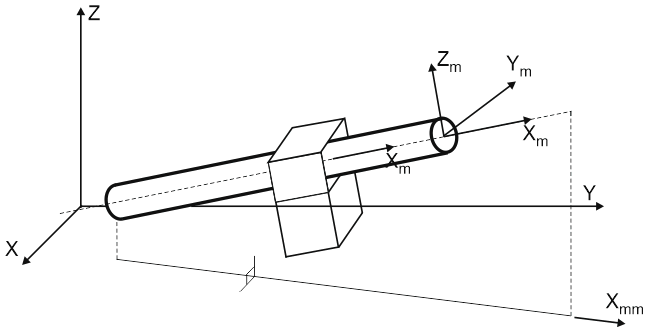
See Global and Local Coordinate Systems
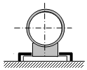
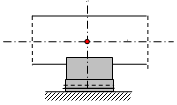
Double-acting guides function similarly to single-directional types but restrict both upward and downward movement. Use for modeling sleeves, pipe penetrations, and similar applications.
Modeled with two double-acting linear restraints (vertical Zm and horizontal Ym) plus frictional restraint along pipe axis Xm.
Suitable for pipes at any angle, including vertical. Friction always acts along pipe axis Xm.
Gaps cannot be specified for vertical pipes. For vertical pipe guides with gaps, use custom restraints.
See "Custom Restraint Links"

Property |
Description |
Name |
Element identifier. When checked, displays in 3D view. |
Weight |
Weight of support components attached to pipe. Applied at attachment node. When building structure allowable loads are specified, calculated load includes piping plus support weight. When support allowable loads are specified, either omit support weight or increase allowable load by support weight value. |
Friction factor |
Friction factor applies to both horizontal sliding and vertical stop surfaces. For different friction factors, use custom restraints. |
Check allowable loads |
PASS/START-PROF automatically compares analysis results against allowable load values. Warnings display when values are exceeded. |
Horizontal gap ∆y, vertical gap ∆z |
∆y gap between pipe and side stops, ∆z gap between pipe and top stop. Bottom gap is always 0. Do not include small installation tolerances (1-3 mm) in model. Multiple small gaps cause iteration convergence problems. Specify only large structural gaps controlled during installation, such as limit stops or seismic stops. Typically >5 mm and limited in number. PASS/START-PROF ignores gaps smaller than 5 mm to maintain iteration stability. For smaller gaps, use custom restraints. G.A. Antaki's piping system qualification guidelines state:
NORSOK L-002 2009 3rd Edition, section 6.17.1:
Small gaps (e.g., 1.5 mm) should not be modeled since they are not verified during installation. Including them reduces model conservatism. Analysis without small gaps provides safer results and better convergence. |
Loads in local axes |
When unchecked, allowable loads reference global coordinate system; when checked, they reference local axes of adjacent element. |
FX, FY, FZ |
Allowable load values for X, Y, and Z axes. |
To insert guide support, select node and use: Insert > Insert Restraint > Guide (Single-directional) or Insert > Insert Restraint > Guide (Double-acting)
or click  or
or  toolbar icon.
To view element properties:
Double-click element in 3D view
Select element
and click  toolbar icon