

|
PASS/NOZZLE-FEM 3.5. Program Manual | |
The model loads are set in the dialog box "Loads" by selecting the appropriate tab (fig. 3.67).
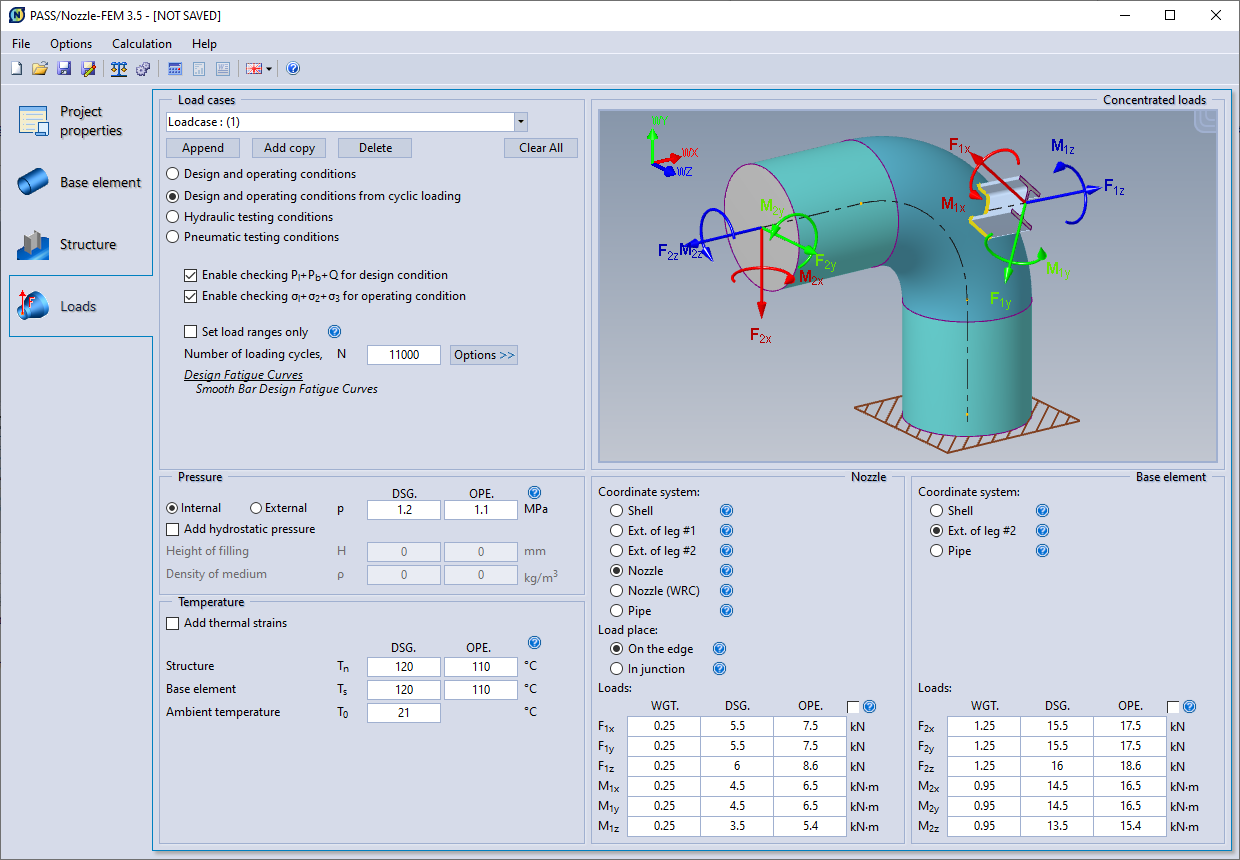 |
| Fig. 3.67. Tab of load setting. |
PASS/NOZZLE-FEM allows you to specify different variants of loads (load cases), displaying the results in one report. The upper dropdown list allows you to switch between the specified load cases, as well as edit their names.
The main edit commands of loadcase list are shown below:
| Command | Description |
| Append | Adds a new load case. All loads will be zero. |
| Add copy | Adds a copy of the current load case. All loads will be identical to the copied load. |
| Delete | Removes current load case. |
| Clear All | Removes all load cases and creates a new empty load case, making it the current one. |
All load cases specified by the user are calculated independently of each other and their results are given in separate sections of the report.
The assessment of the stress-strain state depends on the selected calculation mode, assessments for which are regulated by the relevant code. Each selected code will have its own list of calculation modes:
| Codes | Calculation modes | Description |
| ASME BPVC.VIII.1, ASME BPVC.VIII.2 |
Design and operating conditions | Specifies strength assessments as per part 5 [4]. Upon activation, it will be necessary to set the design and operating load combinations in accordance with the requirements of section 5 [4]. Note that the occasional loads should be taken into account both in design and operating load combinations in accordance with table. 5.3 [4]. Besides, additional data must be specified (calculation options, fatigue curve type, etc.). For more detailed description, see the section "ASME BPVC.VIII.2". |
| Design and operating conditions from cyclic loading | ||
| Hydraulic test conditions | Specifies strength assessments for testing as per part points 5.2.2.5 and 4.1.6.2 [4]. For more detailed description, see the section "ASME BPVC.VIII.2". | |
| Pneumatic test conditions | ||
| EN 13445-3 | Design and operating conditions | Specifies strength assessments as per annex C [6]. Upon activation, it will be necessary to set the design and operating load combinations in accordance with the requirements of appendix C [6]. For more detailed description, see the section "EN 13445-3". |
| Testing conditions | ||
| JB 4732-1995 | Operating conditions | Specifies strength assessments as per part 5 [7]. For more detailed description, see the section "JB 4732-1995". |
| Testing conditions | ||
| GOST 34233.1-2017 | Operating conditions | Specifies assessments as per part 8 [12]. For more detailed description, see the section "GOST 34233.1". |
| Hydraulic test conditions | ||
| Pneumatic test conditions | ||
| Mounting conditions | ||
| GOST 34233.6-2017 | Operating conditions from cyclic loading | Specifies strength assessments as per [15], when vessel or piping component are under cyclic loading. For more detailed description, see the section "GOST 34233.6". |
| GOST 34233.10-2017 | Operating conditions in hydrogen sulphide corrosion medium | Specifies strength assessments as per [16], when vessel or piping component are in hydrogen sulphide corrosion medium. For more detailed description, see the section "GOST 34233.10". |
| PNAE G-7-002-86 | Operating conditions | Specifies strength assessments as per part 5 [17]. For more detailed description, see the section "PNAE G-7-002-86". |
| Testing conditions |
When calculation under cyclic loading, the program allows you to specify the load range. To do this, you must enable the "Set load ranges only" checkbox (fig. 3.68), then only the fatigue assessment will be performed in according to GOST 34233.6 or ASME VIII-2. If the checkbox is disabled, then you must specify dead (weight) and operating loads to define stress range as the difference in stresses from the corresponding load cases. Besides, it is necessary to set the number of cycles during the operation of the vessel and its components, which will determine the allowable stress amplitude, and which also should not exceed the allowable number of cycles for the calculated stress range (fig. 3.68).
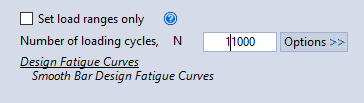 |
| Fig. 3.68. Setting parameters for fatigue assessment. |
To assess the fatigue strength according to ASME VIII-2, a fatigue curve must be specified. To set the fatigue curve parameters, click on the "Options" button (fig.3.68) after which the corresponding dialog box will appear (fig. 3.69). The Fatigue Curve is the diagram of the equivalent stress range versus the number of allowable cycles. The ASME BPVC.VIII.2 code uses two main the curve types:
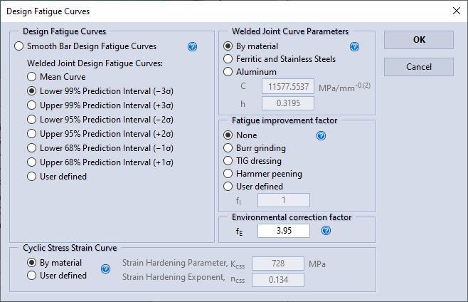 |
| Fig. 3.69. Dialog box of fatigue curve setting. |
When selecting a Welded Joint Fatigue Curve, the parameters described below must be set.
Welded Joint Fatigue Curve Parameters. The Welded Joint Fatigue Curve is defined two main parameters C and h. The parameter C is set in unit of structural stress ΔSess [MPa/mm-0.(2)]. The constants C and h are provided by Table 3-F.2 [4]. The program allows the follow variants:
Fatigue improvement method correction factor to the welded joint fatigue curve. If a fatigue improvement method is performed that exceeds the fabrication requirements of ASME BPVC.VIII.2, then a fatigue improvement factor, fI, may be applied. Therefore default value is 1.0. The fatigue improvement factors presented by the program corresponds 3-F.2.2(b) [4]. An alternative factor determined may also be used if agreed to by the user or user’s designated agent and the Manufacturer.
Environmental correction factor to the welded joint fatigue curve.
The welded joint design fatigue curve does not include any allowances for corrosive conditions and may be modified to account for the effects of environment other than ambient air that may cause corrosion or subcritical crack propagation. If corrosion fatigue is anticipated, a factor should be chosen on the basis of experience or testing by which the calculated design fatigue cycles (fatigue strength) should be reduced to compensate for the corrosion. The environmental modification factor, fE, is typically a function of the fluid environment, loading frequency, temperature, and material variables such as grain size and chemical composition. The environmental modification factor, fE, shall be specified in the User’s Design Specification.
Material hardening parameters for the cyclic stress-strain curve model.
The local nonlinear structural stress and strain ranges, Δσ and Δε, respectively, are determined by simultaneously solving Neuber’s Rule and a model for the material hysteresis loop stress-strain curve given below (see Annex 3-D, 3-D.4 [4]):
$$ \displaystyle\Delta\varepsilon_k = \frac{\Delta\sigma_k}{E_{ya,k}}+2\left(\frac{\Delta\sigma_k}{2K_{css}}\right)^{\displaystyle\frac{1}{n_{css}}}. $$Table 3-D.2 (Annex 3-D) presents $K_{css}$ and $n_{css}$ for some materials (Сarbon and a few Chrome-Molybdenum steels, and a few aluminum alloy). Therefore, the program also allows the user to enter their own values.
PASS/NOZZLE-FEM allows you to set inside or outside pressure on the vessel and its components. When calculating according to ASME VIII-2 or EN 13445-3, the design and operating pressure values are specified as per the code requirements. For the rest of codes, the design pressure is only specified.
The program allows you to set the hydrostatic pressure (pressure of fluid head). To do this, it is necessary to set the medium density ρ and its filling level H, which is measured from the lower point of the base element (fig. 3.70).
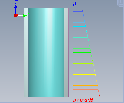 | ||
| Fig. 3.70. Setting the hydrostatic pressure | ||
If a trunnion or support (and its elements) is specified, no pressure is applied to them.
PASS/NOZZLE-FEM allows to set the temperature for individual vessel component: the base element, its adjacent elements (for example, the cylindrical part of head), as well as the nozzle or support. When calculating according to ASME VIII-2 or EN 13445-3, the design and operating temperature values are specified in accordance with the code requirements. For the rest of codes, the design value is only set - the temperature at which the physical and mechanical properties, the permissible stresses of the materials are determined, and the strength calculation is carried out.
To take into account thermal strains, it is necessary to turn on the flag "Add thermal strains", as shown in fig. 3.71. The more details are provided in section "Thermal strains".
 |
| Fig. 3.71. Setting thermal strains |
It is also necessary to set the assembly temperature, which is used when calculating temperature difference and thermal strains, calculating allowable amplitudes under cyclic loading, calculating stiffnesses and SIF (default).
Loads are applied to the nozzle or base shell end, depending on the model configuration. When specifying loads in a junction, they are converted to a statically equivalent load combination and are also applied to the nozzle end. Usually, loads are values that are calculated directly in the piping system design software (example, PASS/START-PROF). These loads should not include the axial component P*A from the pressure, as it is automatically applied by the program.
When calculating according to GOST 34233.6, the design loads and weight loads (dead) are specified.
When calculating according to ASME VIII-2 or EN 13445-3, design and operating load combination, as well as weight loads (dead) are specified.
For the rest of codes, the design loads is only specified.
The dead loads (weight) are used to calculate the stress ranges under cyclic loading of a vessel and its components. They also participate in the assessment of some load combinations as per ASME VIII-2.
When assigning loads at calculation with FEM, it is necessary to pay atten-tion to the fact that forces and moments are applied to the centre of the nozzle head and corresponds to axis directions in selected coordinate system (fig. 3.72). When assigning forces and moments, it is necessary to pay special attention to the signs. Positive values indicate directions designated on the chart. When moving from one coordinate system to another, loads can be recalculated automatically.
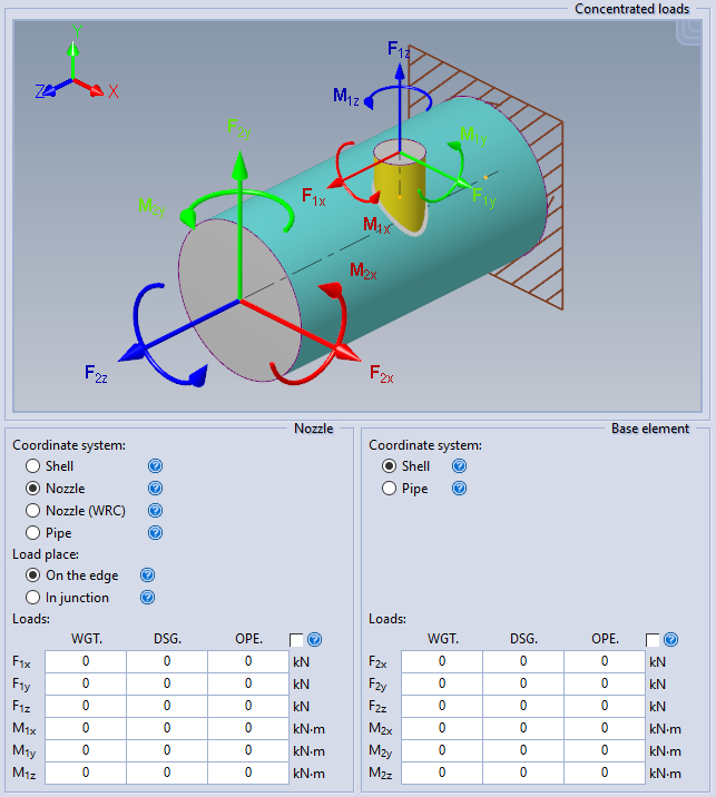 | ||
| Fig. 3.72. Nozzle loads | ||
The following types of coordinate systems (SC) are supported for setting loads:
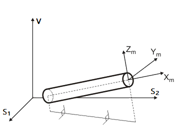 |
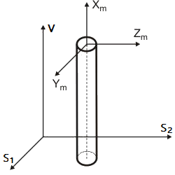 |
| a) | b) |
| Fig. 3.73. Vessel coordinate system (X, Y, Z) and local coordinate system connected to element axes (Xm, Ym, Zm) | |
Design temperature - a temperature at which physical and mechanical characteristics, allowable stresses of materials are determined and strength calculation is carried out.
Design overpressure - internal or external overpressure is assigned.
At activation of calculation in conditions of corrosive hydrogen sulphide environment (possible if the estimation is chosen according to GOST 34233.1-2017 and GOST 34233.10-2017) additional constraints for branch connection construction and loading conditions are implemented, as per normative document [16]. When calculating deflected mode, maximum tensile stresses on the inside sur-face of shell (head) and branch connection are defined. At that a level of allowable stresses is determined in accordance with [12]. Also defined the maximum membrane tensile stresses, whose level is determined in accordance with [12, 16].
PASS/NOZZLE-FEM 3.5. Program Manual
Copyright © 2017-2026, PASS Team