

|
PASS/NOZZLE-FEM 3.5. Program Manual | |
The model of support skirt basically coincides with the head and trunnion radial nozzle model, except for boundary conditions in special calculations.
Table 3.21 shows key features of the base element (shell).
| Table 3.21 | |
 | |
| Feature | Description |
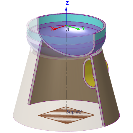
| Reference points: | A: top of head or its cylindrical part; Sup #2: bottom of support skirt. |
| Local support coordinate system (LCS): | Support LCS is inverted to head LCS (see for example Elliptical Head) and coincides with global coordinate system (WCS). |
| Orientation of support and base element: | Support and head are rigidly connected with global CS (fig. 3.65). |
| Constraints (dof): | Point Sup #2 (support end). |
| Shell loads: | Described in section: Elliptical Head. Also, concentrated loads to point A (fig. 3.66): 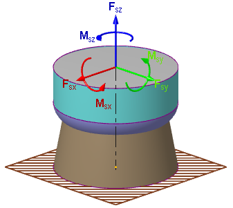 |
| Support loads: | Thermal strains. |
| Special calculations: | Not carried out. |
| Additional capabilities: | Setting the cylindrical and conical shapes of the support skirt. Setting a transitional cylindrical segment of the support skirt: 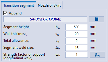 Setting the technological opening in the support skirt: 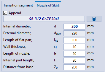 |
PASS/NOZZLE-FEM 3.5. Program Manual
Copyright © 2017-2026, PASS Team