

|
PASS/NOZZLE-FEM 3.5. Program Manual | |
The model of bend stanchion basically coincides with the curved pipe (bend) and trunnion nozzle model, except for boundary conditions in special calculations.
The description of the curved pipe element (bend) is given in the section: Bend (elbow).
Table 3.20 shows key features of the bend stanchion.
| Table 3.20 | |
 | |
| Feature | Description |
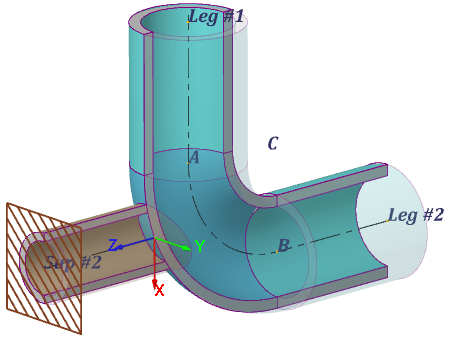
| Reference points: | A: shell start; B: shell end; C: center of bending axial curve; Leg #1: end of cylindrical part at point A; Leg #2: end of cylindrical part at point B; Sup #2: stanchion end. |
| Local stanchion coordinate system (LCS): | Stanchion LCS is according to nozzle LCS and is also permutable CS of leg #1: Aixs X: is directed along longitudinal axis of leg #1. Aixs Y: is directed along normal to bend plane (coincides with Z axis of bend). Aixs Z: is directed along local X axis of bend and is always perpendicular to the leg #1 longitudinal axis (is longitudinal stanchion axis). |
| Orientation in LCS of bend (elbow): | Depends on base element orientation (see Bend (elbow)). Relative to base element is set by the offset parameter $l_d$ from point B (fig. 3.60), while directions of stanchion LCS is keeped. 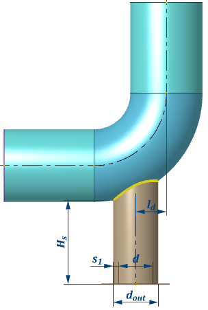 |
| Constraints (dof): | For strength analysis (fig. 3.59): Point Sup #2 (stanchion end).
When calculating allowable loads, stiffnesses and stress intensification factors for leg #2 (fig. 3.61): Point A (or leg #1). 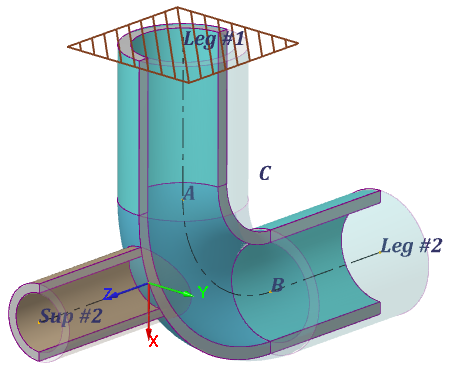
When calculating allowable loads, stiffnesses and stress intensification factors for stanchion junction (fig. 3.62): Points A, B (or legs #1 and #2). 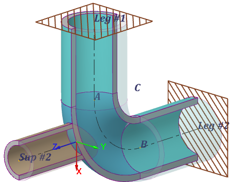 |
| Shell loads: | Described in section: Bend (elbow). Also, concentrated loads to end A or leg #1 for strength analysis (fig. 3.63): 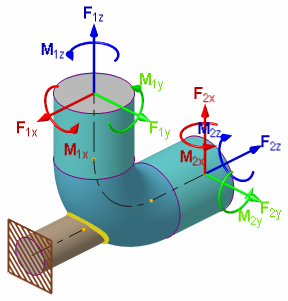 |
| Stanchion loads: | Thermal strains. |
| Special calculations: | They are carried out for stanchion junction and leg #2 (indices 1 and 2 according to fig. 3.64): Allowable loads; Stiffness and flexibility factors; Stress intensification factors. 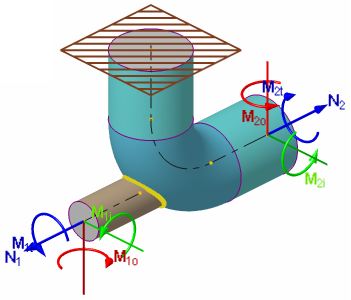 |
| Additional capabilities: | Described in section: Bend (elbow). |
PASS/NOZZLE-FEM 3.5. Program Manual
Copyright © 2017-2026, PASS Team