

|
PASS/NOZZLE-FEM 3.5. Program Manual | |
Table 3.16 shows key features of the base element (shell).
| Table 3.16 | |
 | |
| Feature | Description |
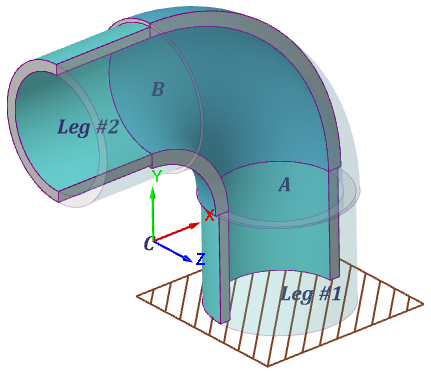
| Reference points: | A: shell start; B: shell end; C: center of bending axial curve; Leg #1: end of cylindrical part at point A; Leg #2: end of cylindrical part at point B. |
| Local shell coordinate system (LCS): | Axis X and Y set bend plane; angle θ of nozzle insertion is taken from this axis toward axis X; Axis Z: shell longitudinal axis. The positive bend angle α rotates point A toward point B around axis Z. |
| Curved coordinate system: | Used to set external loads on the ends or legs of the element: Axis X: is directed to the axial arc center (coincides with the normal to the axial arc). Axis Y: is directed along the normal to the elbow plane (coincides with the elbow Z local axis). Axis Z: is directed along the tangent line to the axial elbow arc. 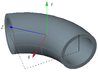 Designated as "CS leg #1" and "CS leg #2", that is computed at points A and B accordingly. For point A, an inverted CS is used so that Z axis is directed towards leg #1. |
| Orientation in WCS: | All axis can be horizontal and vertical according to the shell options: 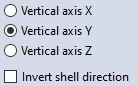 When the "Invert shell direction" option is selected the LCS is rotated around its Z axis by 180°. If a negative bend angle is given (α < 0), then the LCS is rotated around its X axis by 180°. |
| Shell constraints (dof): | The boundary conditions for stress analysis relate from the option state:  Point A or leg #1: option disabled (fig. 3.44), default. Points A, B (legs #1 and #2): option enabled (fig. 3.45).
When calculating allowable loads, stiffnesses and stress intensification factors for a nozzle (fig. 3.45): Points A, B (legs #1 and #2). 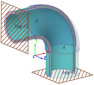 |
| Shell loads: | Inner overpressure. Outer pressure. Hydrostatic pressure. Thermal strains. Concentrated loads to free end (B) or leg #2 for strength analysis (fig. 3.46): 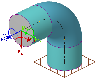 |
| Special calculations: | Allowable loads for end B (fig. 3.47). Stiffness and flexibility factors for end B (fig. 3.47). Stress intensification factors (fig. 3.47). 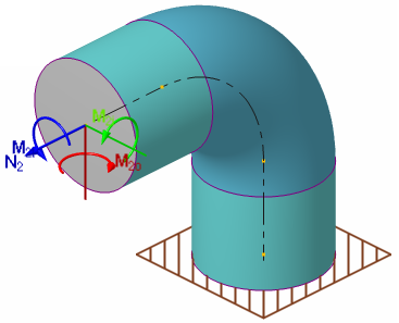 |
| Additional segments: | The base element also allows to specify cylindrical legs #1 and #2. 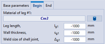 If a negative value of the leg length is specified, then it is calculated as follows: $$ l_g = 3 D_{out}.$$If negative values of the leg thickness and the weld size are given, then they are accepted as for the base element. |
PASS/NOZZLE-FEM 3.5. Program Manual
Copyright © 2017-2026, PASS Team