Straight pipe
To add
a new straight pipe, click the button  of Components
toolbar
or use the corresponding item of "Insert
- Component" menu. Please note that the new component
is added to the project tree after the currently selected element. Therefore,
to add a new component after an existing one, select it in the project
tree or in the graphic window and add the new component. If you need to
add a new component to the beginning of a branch, select the branch in
the project tree and add the new component.
of Components
toolbar
or use the corresponding item of "Insert
- Component" menu. Please note that the new component
is added to the project tree after the currently selected element. Therefore,
to add a new component after an existing one, select it in the project
tree or in the graphic window and add the new component. If you need to
add a new component to the beginning of a branch, select the branch in
the project tree and add the new component.
The straight pipe component is used to model and calculate friction losses in straight pipes, as well as hydrostatic pressure differences on them.
After adding a component, its characteristics will be displayed in the Object Properties Window:
name - by default, when entering a new piping component, its name matches the type, but if necessary, it can be changed in this field. Specify the name that you would like to see for this component in reports with calculation results. To display the component name on the piping diagram, click the corresponding button to the right of its name;
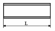
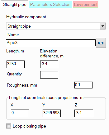
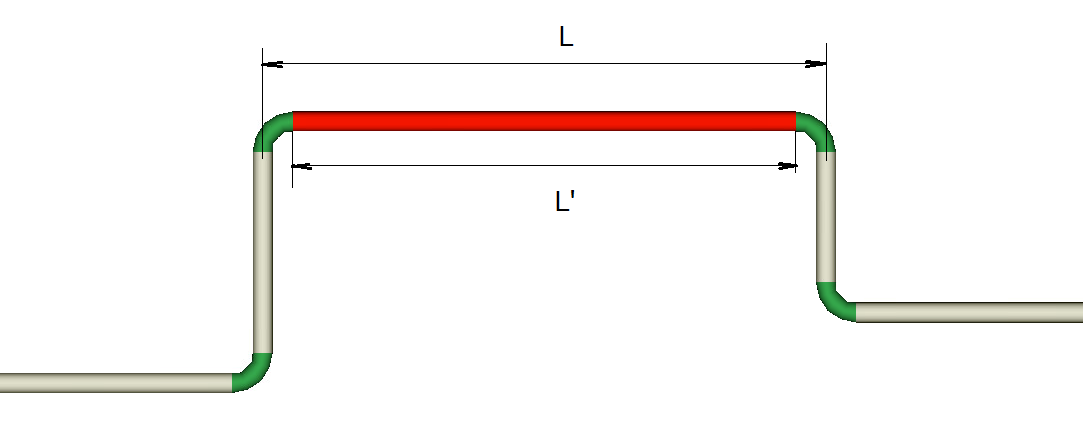
length and elevation difference/lengths of coordinate axes projections — the length and orientation of a pipe are most conveniently specified using the lengths of the projections of a given pipe section onto the X, Y, and Z coordinate axes. When specifying the lengths of the projections of a pipe, imagine that the coordinate origin is at the starting point of a given pipe and specify the X, Y, and Z coordinates of the end point of a given pipe as the projection lengths. The lengths of the projections onto the coordinate axes can be either positive or negative (the positive directions of the X, Y, and Z coordinate axes are displayed in the lower right corner of the graphics window). After entering the projections, the length and the elevation difference of the pipe will be calculated automatically. Please note that the length of a pipe section must be specified as the actual length of the pipe from its beginning to the end ("from weld to weld" of the connection of this pipe with adjacent pipeline elements). That is, for example, for the pipe marked in red in the figure below, the length must be specified as L' = L - 2*R, where L is the distance between the axes of the pipes before and after the current one, R is the radii of the bends.
It is especially important to set the correct lengths when modeling vertical and inclined pipes (since their vertical projection determines the hydrostatic losses in the pipe, which are usually quite large for a liquid fluid, and therefore it is important to take them into account very accurately) and when modeling pipelines with closed loops, which, if the lengths are set incorrectly, will have gaps and will look "unsightly". The elevation difference of a pipe is, by analogy with its length, the vertical distance between the center of the outlet and inlet cross-sections of the pipe (a positive value means that pipe goes upwards, a negative value - downwards).
In addition, after entering the projection lengths, the total length of the section can then be adjusted. This is useful when specifying sections that are not strictly directed along any of the X, Y or Z axes, but at an angle between them. For example, if you need to add a 30-meter-long pipe section at an angle of 45° between the X and Z axes, specify the equal projections on the X and Z axes of any value, then change the calculated pipe length to 30 meters - the corresponding projections on the X and Z axes will be calculated automatically. Similarly, you can change the elevation difference of a pipe - the pipe projections in this case will also be recalculated in accordance with the entered elevation difference.
quantity - this parameter is usually not used for a pipe section. It is used for other piping components (for example, for valves or bends) when modeling several identical elements. In this case, you can enter the quantity of these elements in this field and the hydraulic resistance and heat losses of this element will be multiplied by the specified value. For pipe sections, specifying "N sections by M meters" does not make sense, since for a pipe section you can simply specify its total length N*M;
roughness of the inner surface of the pipe - initially this parameter is set for the pipeline and/or its branches, therefore, by default, the same roughness value will be set for the section and used in the calculation as in the branch to which it belongs. However, if necessary, different roughness values can be set for different sections of the branches (for example, if part of the pipeline is "old", part is "new" or if the pipeline consists of pipes of different materials, etc.);
loop closing pipe - this option is used when modeling pipelines with closed loops. Any one of the pipes of the closed loop can be assigned as a loop closing pipe by enabling this option for it. In this case, entering the projection lengths for this section is blocked, and the program calculates what the projections of this pipe should be so that the loop closes perfectly (the loop closing pipe is shown in the isometric piping diagram as a pale gray line). To then "accept" the projection lengths calculated by the program and determine the length and elevation difference of the pipe, click the "Recalc by graphics" button (in the form of a blue "calculator") for this pipe:
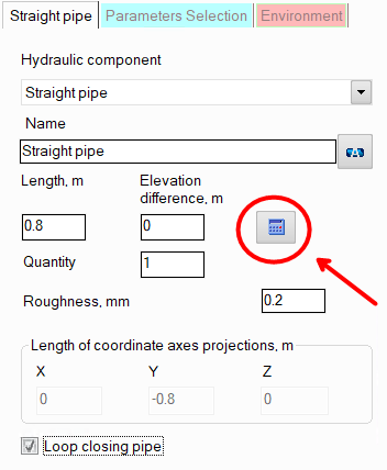
Please note that this button is displayed only if the "Scaled graphic view" and "Show all components" options are enabled in the pipeline graphic view options (on the View Options toolbar) and the "Precise graphic representation of scaled view" option is enabled in the program settings. Otherwise, it is not recommended to use the "Loop closing pipe" option, since when the display of piping components and/or scaled view are disabled, the calculation of the projections of the closing pipe may be incorrect. It should also be noted that if the "Recalculate elevations and angles on graphic before every analysis" option is enabled in the program settings, there is no need to click the "Recalc by graphics" button for each closing section. At the calculation, the parameters of all closing pipes in the pipeline will be automatically recalculated according to the projection lengths defined by the program.
The "Loop closing pipe" option is recommended to be used in cases where you are not sure of the correctness of the entered length/projections of pipes in closed loops. If the closed loop is correctly modeled, there is no need to use this option. More information about modeling pipelines with closed loops can be found here.