
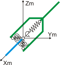
Model custom expansion joints using linear and rotational restraints at pipe connection nodes. Remove restraints to allow movement in specific directions or replace with elastic restraints having defined flexibility. Linear restraints prevent mutual pipe cross-section displacement along and perpendicular to the pipe axis, but permit rotation. Rotational restraints prevent mutual pipe cross-section rotation, but allow displacement.
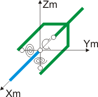
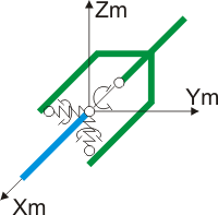
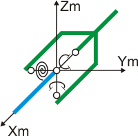
Cutting a pipe at cross-section А-А (fig. 2.а) and connecting both sections with six restraints (three rotational and three linear) maintains full structural integrity (fig. 1).
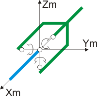
Fig. 1. Internal restraints creating rigid pipe connection in 3D system
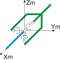
For clarity, consider a 2D system (fig. 2). Connecting pipe ends at cross-section А-А requires three restraints for planar structures: two linear (axial and transverse anchors) and one rotational restraint (fig. 2.b or c). Since rigid rotational restraints are difficult to depict, fig. 2.b and c show equivalent parallel rigid linear restraints (horizontal and vertical).
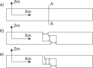
Fig. 2. Internal restraints creating rigid pipe connection in 2D system
Model any expansion joint function by removing specific internal restraints at the pipe cross-section:
Remove one linear restraint preventing transverse displacement to model a lateral expansion joint (fig. 3.а), allowing sliding perpendicular to pipe axis.
Remove one rotational restraint to model an angular expansion joint (fig. 3.b), allowing pipe rotation.
Remove one linear restraint preventing axial displacement to model an axial expansion joint (fig. 3.c), allowing movement along pipe axis while restricting transverse motion and rotation.
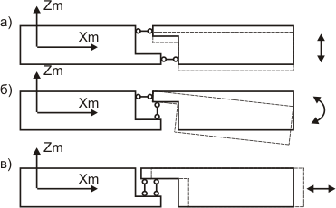
Fig. 3. Removing one internal restraint models lateral (a), angular (b) and axial (c) expansion joints
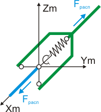
In practice, restraints are typically replaced with elastic restraints having specific flexibility (fig. 4). Frictional forces in restraints are usually negligible.
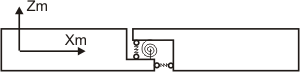
Fig. 4. Axial, transverse, and rotational elastic restraints in expansion joint
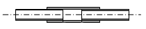
These models are idealized and may not match actual structures, particularly for axial and lateral expansion joints. Real expansion joint properties are condensed to a single node connecting two pipe elements, which is an approximation. For example, fig. 4 shows a lateral expansion joint model with intermediate pipe.
Actual expansion joint length L is substantial. The model condenses relative pipe end displacement to a single point at the expansion joint center (fig. 5.a.c), with pipe elements of length L/2 on either side (fig. 5.b.d).
Lateral expansion joint models restrict rotation and axial displacement. Actual structures may not provide these restraints without proper support configuration. For example, without adequate supporting restraints (fig. 6) or special structures like ties (fig. 7), the lateral expansion joint model (fig. 5, а.c) may not match actual behavior, as adjacent pipes can rotate and move axially.
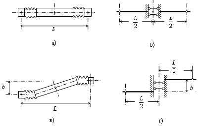
Fig. 5. Lateral expansion joint with intermediate pipe
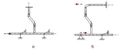
Fig. 6. Lateral expansion joint placement on bends ensuring proper function (restricting axial displacement and rotation of adjacent pipe ends)
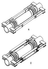
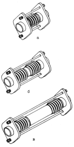
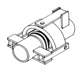
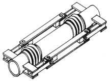
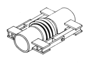
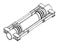
Fig. 7. Heavy (left) and light (right) lateral expansion joints restricting axial displacement and rotation
These considerations apply to axial expansion joints as well. For axial bellows to restrict all movements except axial displacement, adjacent pipe ends require proper restraint (fig. 8). Without these restraints, the bellows functions as a Universal Expansion Joint.
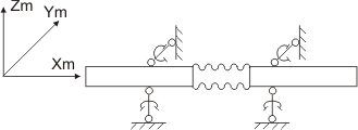
Fig. 8. Axial bellows configuration ensuring proper function
PASS/START-PROF includes standard expansion joints to simplify modeling. These contain pre-defined restraint combinations and automatically align restraint directions with local element axes. Standard expansion joint restraints are described below.
See "custom restraints" for detailed restraint information and directions.
Restraint type symbols:
 - rigid linear
double-acting restraint
- rigid linear
double-acting restraint
 - rigid rotational
double-acting restraint
- rigid rotational
double-acting restraint
 - elastic rotational
restraint
- elastic rotational
restraint
 - elastic linear
restraint
- elastic linear
restraint
Thrust force indicated with arrows
Restraint type abbreviations:
R - rigid double-acting
E - elastic
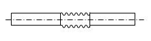
Axial expansion joints allow displacement along pipe axis while restricting rotation and transverse displacement. Proper function requires specific expansion joint design or adequate support placement. Include internal pressure thrust force for bellows.
PASS/START-PROF standard axial expansion joints replace axial linear restraint with elastic restraint, remove two rotational restraints (accommodating potential skew), and include internal pressure thrust force Fthrust.
Allows elastic rotation around vertical and horizontal axes. Restricts axial and transverse displacement.
Allows transverse displacement along vertical and horizontal axes (pipe offset). Restricts axial displacement and all rotation.
Standard PASS/START-PROF expansion joints cannot model all real structures. Often requires creating custom expansion joints. Custom expansion joint examples:
Unlike 3D gimbal joints, allows rotation only around horizontal axis. Restricts vertical axis rotation, axial displacement, and transverse displacement.
Manufacturers discourage planar expansion joints due to difficulty in proper tie rod alignment. Incorrect alignment causes high bending moments on ties, potentially jamming or failing them. Required tie direction may change significantly between operating conditions.
Unlike 3D lateral joints, allows displacement only along vertical axis (vertical offset). Restricts horizontal displacement, axial displacement, and all rotation.
See comments for planar angular expansion joints.
Universal expansion joints are bellows with end connections for pipe attachment. They lack built-in rotation or offset capability. With proper support, they function as axial expansion joints with limited skew tolerance.
Universal expansion joints remove three linear restraints (axial and transverse) and two rotational restraints. Only one internal restraint remains - torsional restraint preventing rotation around pipe axis.