When modeling piping systems, you often need to add branch connections along the main run axis. This is straightforward when the pipe axis aligns with a global coordinate system axis. However, when the pipe axis is angled relative to multiple global axes, placing a perpendicular branch requires manual calculation of element projections. The rotate element function simplifies this process.
Select the run element where the branch
will connect. Click the  toolbar icon. The cursor
appearance changes. Select the branch node, which must be one of the selected
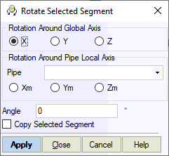
element's end nodes. The rotation dialog appears:

Select the rotation axis. You can choose a global axis or one of the selected element's local axes. The positive direction follows the element's node numbering sequence. For example, direction 4-14 is positive, while 14-4 is negative.
Enter the rotation angle in degrees in the "Rotation angle around selected axis" field.
Counter-clockwise rotation from the positive axis direction is positive; clockwise rotation is negative.
Check "Copy selected element" to create a rotated copy of the element. Leave unchecked to rotate the original element, creating a bend instead of a branch.
Click OK to apply. The system prompts whether to insert a tee fitting at the branch node.
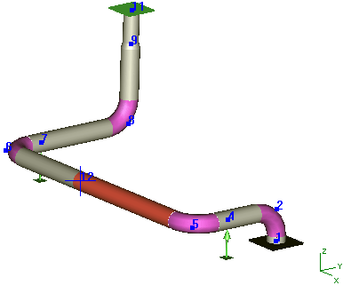
Add a stub-in branch at node 12, angled 45° from the horizontal plane.
Select element 12-5 and click the  toolbar icon.

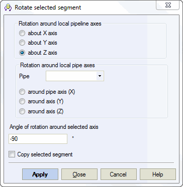
After the cursor changes, select node 12. Configure rotation parameters in the dialog: Z-axis, rotation angle -90°, check "Copy selected element".


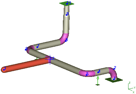
Branch 12-3 now lies in the horizontal plane. Rotate it 45° from this plane.
Select element 12-3 and click the  toolbar icon.
Select node 12 and configure rotation around element 12-5 by 45° counter-clockwise.
Do not check "Copy selected element" since you need to
rotate the original element.

Click OK to create the element. Typically, branch dimensions (diameter, wall thickness, length) differ from the run. Modify these by double-clicking the element and editing properties in the dialog.

The rotation operation also affects these associated elements:
Pipe element uniform loads
Node concentrated forces
Restraints in custom supports
Restraints in custom expansion joints
Nodal displacements
Support displacements
Tools > Rotate Selection
