
Learn about PASS/START-PROF pipe stress analysis software
PASS/START-PROF provides three methods for modeling vertical pressure vessels:
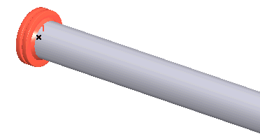
1. Using nozzle element at pipe end node. This method assumes the pressure vessel is rigid (global beam flexibility not considered), except when using the "FEM" option. Thermal expansion is automatically accounted for—no need to model the vessel with rigid elements or restraint movements.
Use this method only for simple cases without significant horizontal loads such as seismic or wind forces.
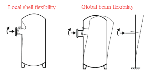
2. Model the vessel using cylindrical shell element (3). Use rigid element (1) to represent the distance between nozzle and vessel axis intersection point. Insert nozzle element (2) between pipe and rigid element. This classic method accounts for both local shell flexibility and global beam flexibility.
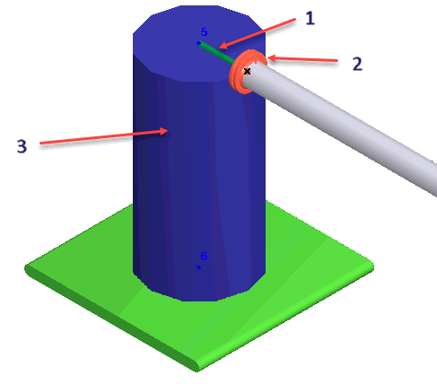
1 - Rigid Element, 2 - Nozzle Element, 3 - Cylindrical Shell Element
3. This efficient method provides identical results to method #2 with less modeling effort. Model the vessel using cylindrical shell element and insert nozzle element at the connection point between pipe axis and cylindrical shell (node 1). PASS/START-PROF automatically adds internal rigid elements. Both local and global flexibilities are properly accounted for.
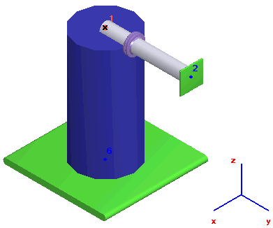
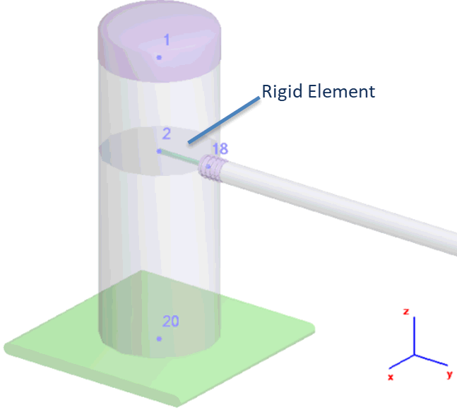
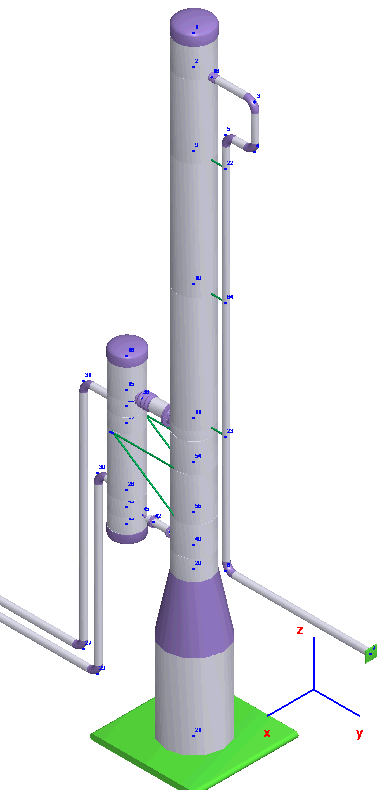
Methods 2 and 3 support complex equipment configurations with multiple nozzles connected to a single vessel.
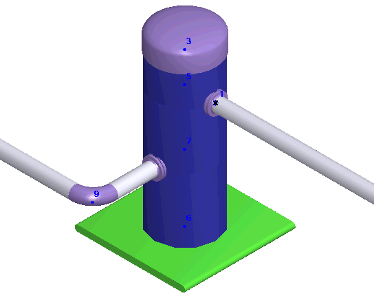
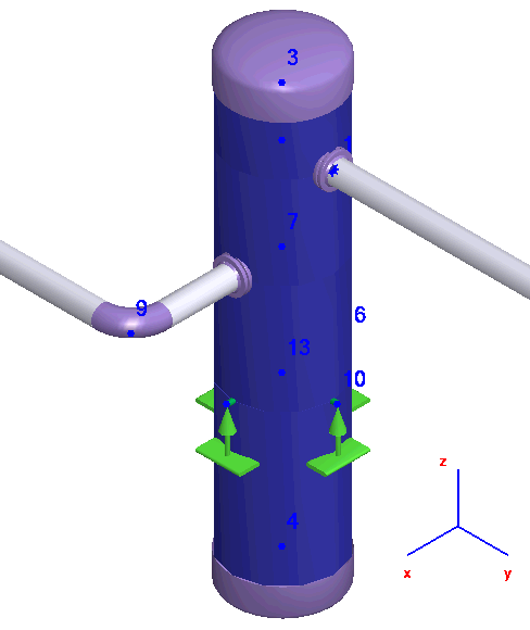
More realistic vessel-to-foundation connections can be modeled:
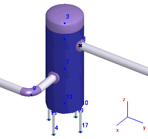
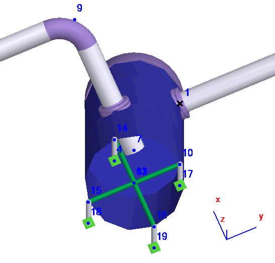
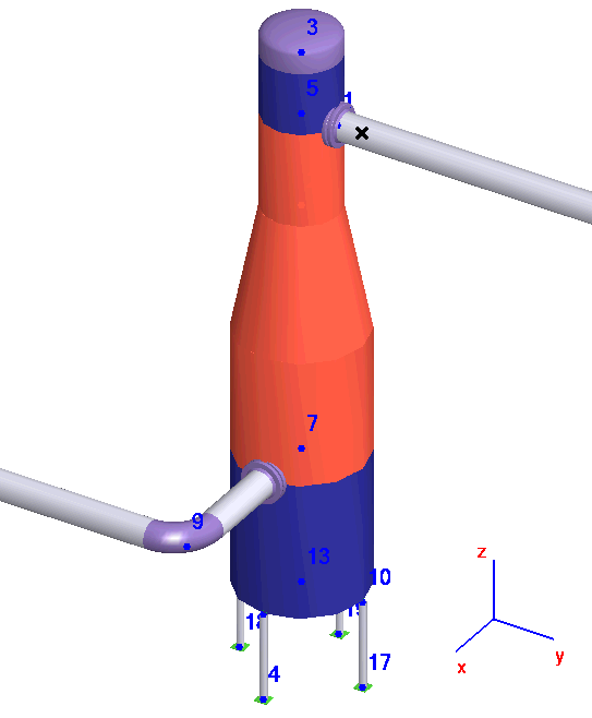
PASS/START-PROF accommodates vessels of various designs:
