
Read about START-PROF pipe stress analysis software
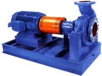
The Pump API 610 element models pumps and checks nozzle loads per API 610 / ISO 13709 standards. Each pump object connects to one or two nodes. PASS/START-PROF checks allowable loads for individual nozzles and the complete pump assembly. Results display in the Loads on Nozzles and Equipment Table. See also How to Reduce Nozzle Loads in START-PROF.
Two modeling approaches are available:
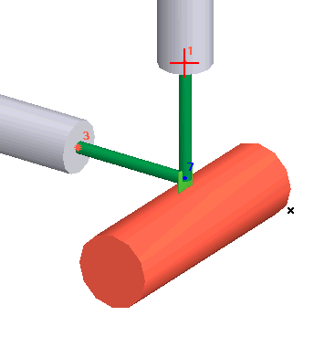
1. Place pump nozzles at pipe end nodes. Nozzles automatically model as fixed anchors with thermal expansion simulated as anchor movements.
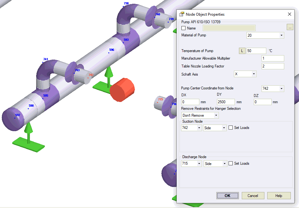
2. Place pump nozzles at intermediate nodes. Model the pump structure using rigid elements, cylindrical shells, and other components. Thermal expansion models through element temperature changes.
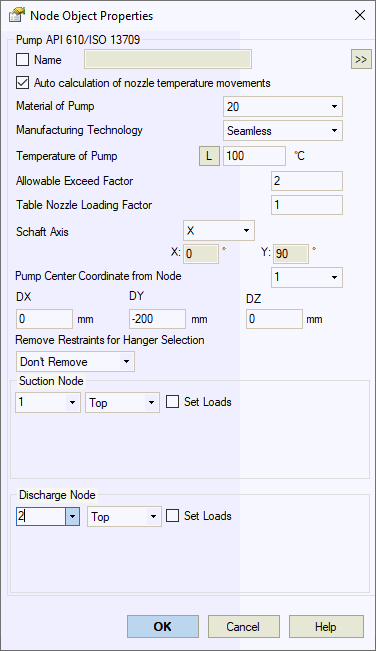
Property |
Description |
Name |
Element name. When checked, displays in 3D view. |
Auto calculation of nozzle temperature movements |
Automatically calculates nozzle movements as DX*Alpha*(T-Ta), DY*Alpha*(T-Ta), DZ*Alpha*(T-Ta), where Alpha is thermal expansion coefficient from material properties, T is equipment temperature, Ta is ambient temperature, DX/DY/DZ are distances from pump center. Uncheck to specify movements manually. |
Material |
Material selection from materials database. |
Manufacturing technology |
For ASME B31.1, ASME B31.3, DL/T 5366-2014, seamless pipe uses Wl=1.0. Electric-welded pipe Wl values come from database. More... For GOST 32388-2013, pipe properties vary based on seamless/welded construction from different materials databases. |
Temperature |
Pump operating temperature. More... This property varies by operation
mode. Click |
Allowable exceed factor |
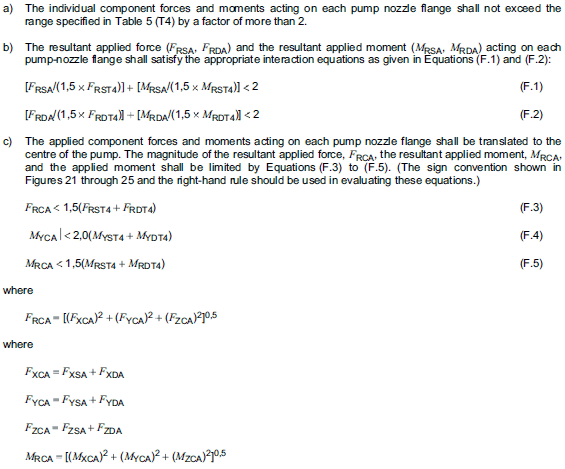
Default: 2.0. Adjust per manufacturer requirements. Used for Annex F analysis. Nozzle loads must not exceed table values multiplied by this factor. Set to 1.0 to disable Annex F.
|
Table Nozzle Loading Factor |
Default: 1.0. Adjust per manufacturer requirements. Multiplies all table allowable values by this factor.
|
Fshaft Direction |
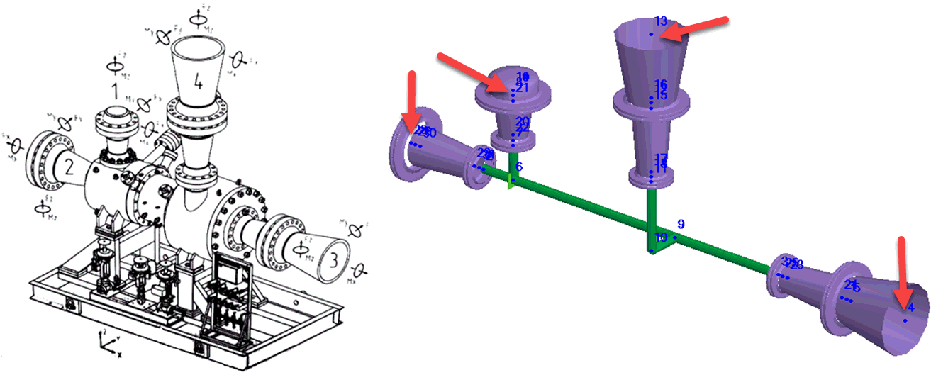
Defines pump shaft X-axis orientation per standard drawings.
|
Pump Center Point Offsets |
Reference node and offsets to pump center (point 3 in drawings above). |
Remove restraints for hanger selection |
When activated, removes specified restraints during spring hanger selection weight run. Restraints remain active during main analysis. Options:
|
Suction Nozzle Discharge Nozzle |
Node connections for suction and discharge nozzles. Specify nozzle type (Top, Side, End). Select "Set Custom Loads" to manually input loads if opposite side piping is not modeled. |
Set Loads |
Apply manual loads to second nozzle when only one nozzle is modeled, enabling Annex F compliance checks. |
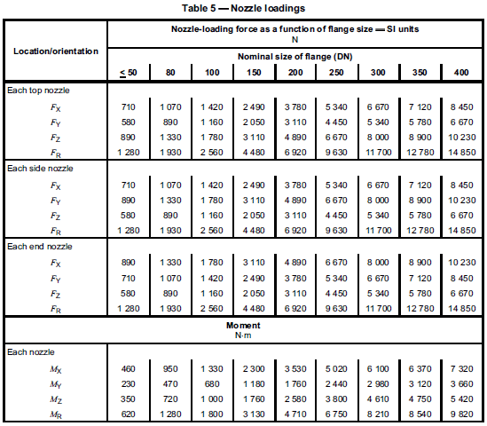
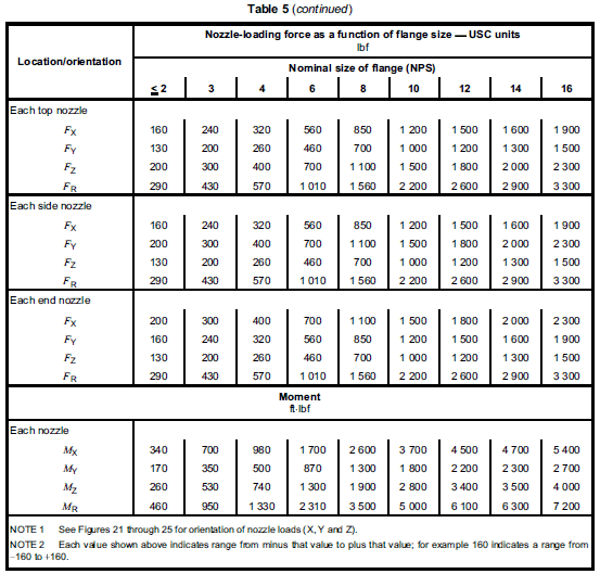
Pump allowable loads reference Table 5 of API 610.
Code requirements:

START-PROF performs additional Annex F compliance checks:

To insert a pump, select the desired node and use: Insert > Equipment > Pump API 610
or click the  toolbar icon.