
Learn more about PASS/START-PROF pipe stress analysis software
Insert a node at the bend tangent point and add a resting support.
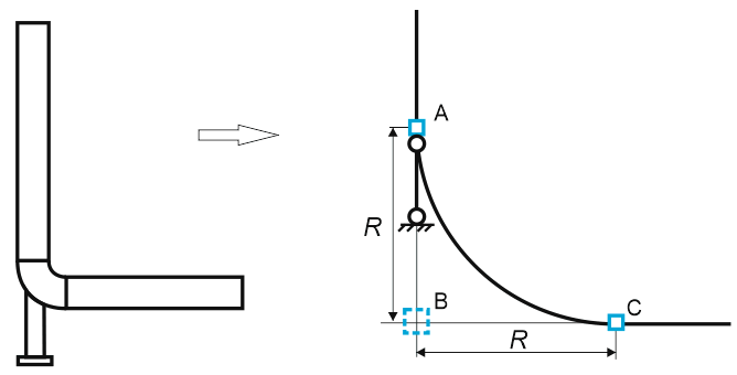
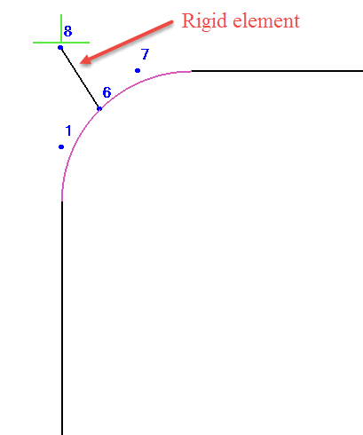
To account for support thermal expansion, apply an upward displacement to the resting support equal to the expansion value. For improved accuracy, include a rigid element (with thermal expansion) matching the bend radius, then add the trunnion pipe.
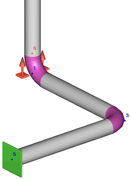
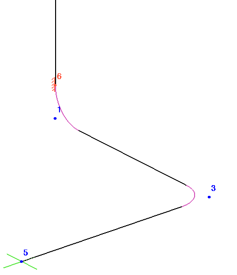
The advanced model is automatically generated when using the Trunnion on Bend element.
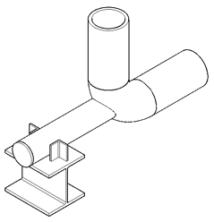
To model a trunnion, insert a node at the bend tangent point.
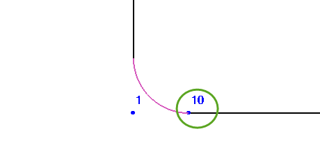
Add a pipe section (trunnion) at this node with zero internal pressure and zero fluid weight. Do not insert a tee fitting at the intersection. Place a support at the trunnion end. For better accuracy, include a rigid element equal to the bend radius before adding the trunnion.
Approximate temperature gradient along the trunnion length:
Non-insulated pipes: 40°C per inch (25 mm)
Insulated pipes: 4°C per inch (25 mm)
Alternatively, use one-third of the operating temperature for the trunnion.
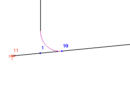
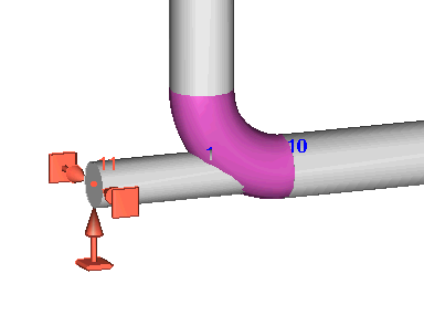
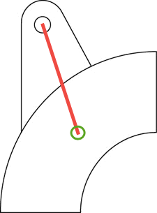
This configuration can be modeled as shown in Example 1. Below is an alternative approach.
Insert a node at any point along the bend axis.
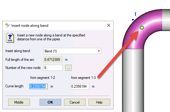
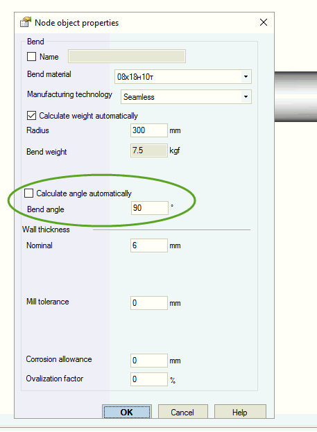
This creates an additional node, splitting the bend into two segments. Set each segment to 90 degrees, indicating they form a single 90-degree bend. This angle determines the flexibility factor (k-factor).
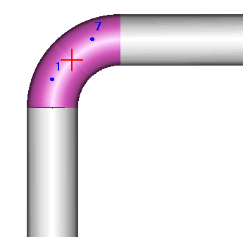
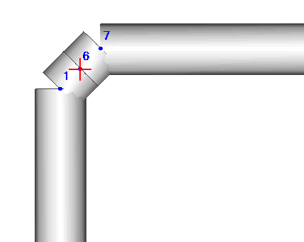
Add a rigid element with zero weight and attach a hanger to its end. Do not insert a tee fitting.
