
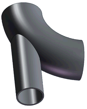
A trunnion on a bend is a pipe connected directly to the bend without an opening. The trunnion element can be placed at the intersection node of three pipe elements, similar to a tee connection. This configuration allows for comprehensive stress and flexibility analysis at the junction point. After analysis, detailed reports can be exported to MS Word.


Property |
Description |
Name |
Element identifier. When checked, the name displays in the 3D view. |
SIF |
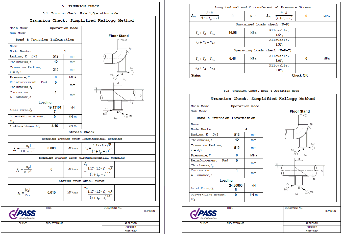
Displays the h-value, stress intensification factors, and k-factors for the trunnion. |
Radius, R |
Bend mean radius (0.5D < R < 10D). Long radius: 1.5D, short radius: 1.0D. |
Calculate weight automatically |
When selected, calculates the reducer weight as the torus volume using the wall thickness of the adjacent pipes. |
Analysis type |
Select the trunnion analysis method: simplified Kellogg method, original Kellogg method, or automated SIF and k-factor calculation using PASS/NOZZLE-FEM finite element analysis. |
Weight |
Bend weight (including flanges), excluding insulation and fluid content. Values are set per applicable standards without overload factors. Fluid and insulation weights, including their respective overload factors, are automatically calculated from adjacent pipe data. |
Longitudinal Weld Joint Efficiency Factor, E |
Longitudinal weld joint efficiency factor. More information... |
Calculate angle automatically |
Defines the bend angle for flexibility factor (k-factor) calculations. Enable this option by default for automatic angle calculation. Disable this option when modeling a support on a bend that has been split into multiple segments. In this case, specify the total bend angle for the entire bend, not for individual segments. |
Angle |
|
Manufacturing technology |
For ASME B31.1, ASME B31.3, and DL/T 5366-2014, seamless pipes use Wl=1.0. For electric-welded pipes, Wl is retrieved from the material database. More information... When using GOST 32388-2013, pipe properties are sourced from different material databases based on pipe type (seamless or welded). |
Material |
Material selection from the material database. |
Presence of flanges |
Specify the number of flanges. Flanges act as rigid elements that inhibit cross-section ovalization. Flange presence affects both flexibility factors and stress intensification factors.
|
Nominal wall thickness, S |
Nominal (actual) pipe wall thickness. |
Mill tolerance, С1 |
Manufacturing tolerance for wall thickness. More information... For analysis per RD 10-249-98 (section 3.3.2.8), specify three mill tolerance values (С1=С11+С12): external, neutral, and internal bend sections, with a differential equal to С12. More information... |
Corrosion and wear allowance, С2 |
Additional wall thickness allowance for corrosion and erosion. More information... |
Refresh SIF and k using FEA |
|
SIF |
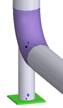
When you insert a trunnion on a bend object and run an analysis, PASS/START-PROF automatically generates an advanced secondary model. The software inserts a rigid element into the bend at node 33. A vertical pipe element (the trunnion) is inserted at node 35. You must add a support at node 36.
PASS/START-PROF automatically applies stress intensification factors (SIF) and flexibility factors (k) at the intersection node 35.
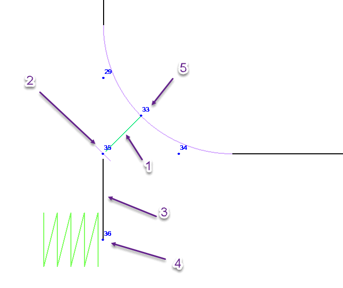
1 - Rigid element, 2 - Trunnion flexibility and SIF, 3 - Pipe element, 4 - Support, 5 - Bend centerline node
Insert > Insert Bend > Bend with Trunnion