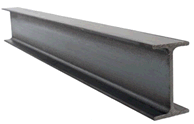

Use beam elements to model steel structures and supports.
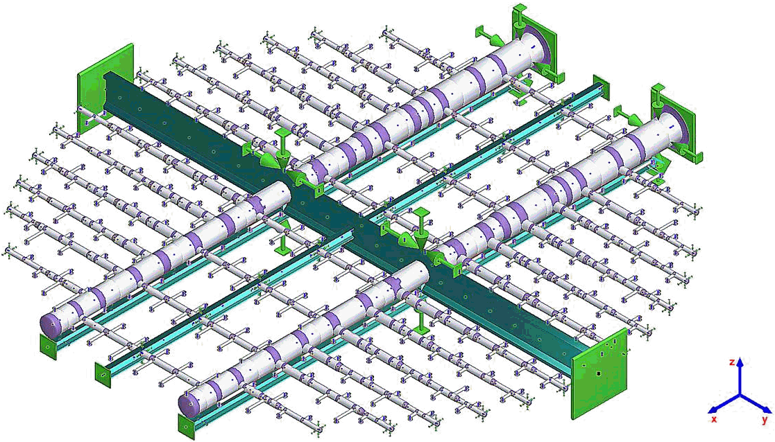
Spray system FRP pipe in power plant FGD tower. Beam structures support the pipe system, providing accurate vertical deflection analysis.
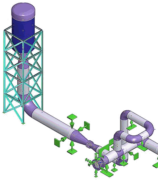
Compressor blowdown pipe with silencer support. Structural lateral deformation reduces nozzle loads and anchor loads.
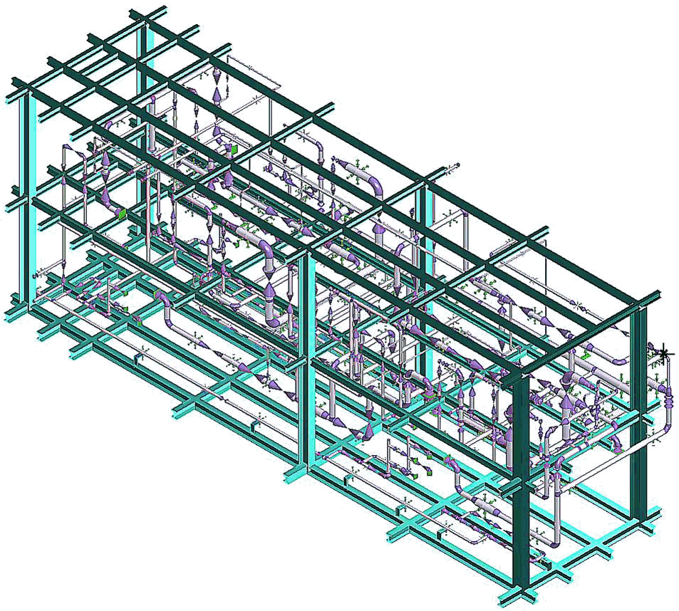
Oil & gas plant skid model
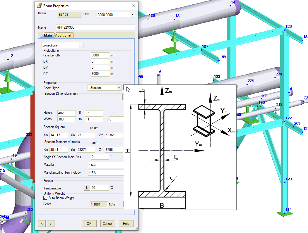
Property |
Description |
Name |
Element identifier. Sort and select elements by name in the project tree. |
Projections\sphere\cylinder1 |
Projections - Element dimensions
defined by global coordinate projections DX, DY,
DZ. |
Beam Type |
Cross-section profile type
|
Section Dimensions |
Height,
Width, tf, tw - Section geometry parameters. Click Section Area: Xm
- Cross Section Area Moment
of Inertia: Simple profiles (Solid rectangular bar, Solid round bar, Circular tube) calculate properties automatically. For other profiles, use the beam section database. If database values are missing, PASS/START-PROF calculates them using simplified equations. |
Angle of section main axis |
Angle
between local Zm axis and global Z axis.
|
Material |
Material from the materials database. Used for thermal expansion calculations. |
Manufacturing technology |
Selects the appropriate material database section. |
Operation temperature, Тop |
Temperature in operating mode. Used for thermal expansion analysis. More... |
Uniform beam weight |
Distributed weight along beam element. |
To insert a beam element:
Insert > Beam Element (select target node first)
To view element properties:
Double-click the element in the 3D view
Select the
element and click  in the toolbar