Learn more about START-PROF pipe stress analysis software
Analysis results appear in the Loads on Nozzles and Equipment Table. See also How to Reduce Nozzle Loads in START-PROF
Property |
Description |
Name |
Element identifier. When checked, displays in 3D view. |
Auto calculation of nozzle temperature movements |
Calculates nozzle movements automatically using ΔX=L/2·α·(T-Ta), ΔY=DY·α·(T-Ta), ΔZ=DZ·α·(T-Ta), where α is the thermal expansion coefficient from material properties, T is equipment temperature, Ta is ambient temperature, L is tube length, and DY, DZ are distances from floating header center. When disabled, specify movements manually. |
Material of Heat Exchanger |
Material selection from the materials database. |
Manufacturing technology |
For ASME B31.1, ASME B31.3, DL/T 5366-2014, seamless pipe always uses Wl=1.0. Electric-welded pipe Wl comes from the database. More... When using GOST 32388-2013, pipe properties are sourced from different materials databases based on pipe type (seamless or welded). |
Temperature of Heat Exchanger |
Heat exchanger operating temperature. More... This
property is modifiable per operation
mode. Click |
Factor for Nozzle Allowables |
Default: 1.0. Adjust per manufacturer specifications. Multiplies nozzle allowable loads from Table 4. |
Factor for Floating Header Allowables |
Default: 1.0. Adjust per manufacturer specifications. Multiplies floating header allowable loads per section 7.1.10.2. |
Factor for Whole Heat Exchanger Allowables |
Default: 3.0. Adjust per manufacturer specifications. Multiplies whole heat exchanger allowable loads per section 7.1.10.3. |
Axis of Heat Exchanger |
X-axis orientation along tube direction per drawing:
|
Tube Length |
Tube length L used for axial thermal expansion calculation: ΔX=α(Tope-Tambient)L/2
|
Remove restraints for hanger selection |
When enabled, removes specified restraints during weight case for spring hanger selection. Restraints remain active during main analysis. This technique isolates weight loading from nozzle elements, allowing springs to carry load at zero displacement under pure weight.
|
Floating Header |
Assign node numbers connected to floating header. Click "Add" for additional headers. |
Allowable Loads |
Available options:
|
When nozzles are located at pipe end nodes, START-PROF automatically models thermal expansion along X, Y, and Z axes.
All nozzles are modeled using fixed anchors.
When the exchanger body is modeled using rigid elements, thermal expansion is simulated through rigid element expansion.
Nozzle loads are compared against Table 4 allowable values.
Floating header load sums are verified against section 7.1.10.2 criteria.
Total loads from all floating headers are checked against section 7.1.10.2 values multiplied by 3.

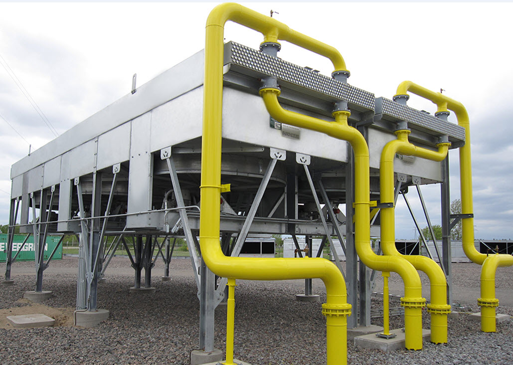
To insert an air cooler: Select the target node, then choose Insert > Equipment > Air Cooler Nozzle API 661/ISO 13706
 to view values across
all operating modes.
to view values across
all operating modes.