

|
PASS/NOZZLE-FEM 3.5. Program Manual | |
In calculation results per FEM the following data is displayed: mesh level Km and its factor of safety, allowable stresses and modulus of elasticity for materi-als of nozzle, pad (if any) and shell (head).
Finite element model of branch connection will be deduced. An example of tilted branch connection into conical shell is given on fig. 3.76. One can see a load application point (in red) and model fixing points (in yellow).
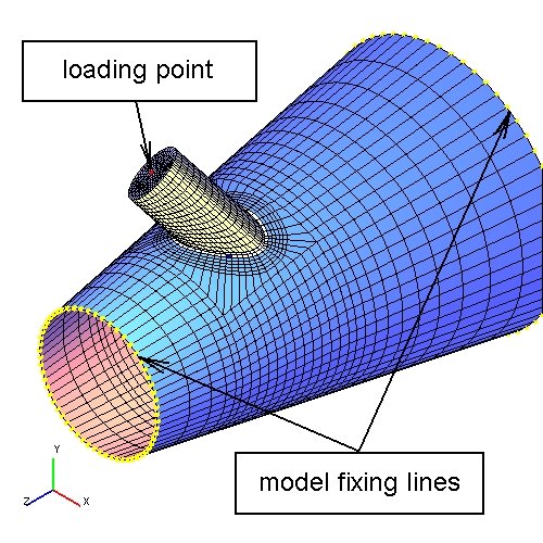 |
| Fig. 3.76. Finite element model of branch connection |
By pressing  button more detailed branch connection layout is dis-played,
while pressing
button more detailed branch connection layout is dis-played,
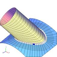
while pressing  button deformed model is displayed (fig. 3.77).
 |
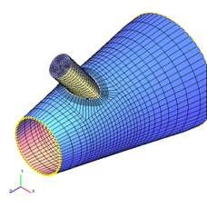 |
| Fig. 3.77. Finite element model of branch connection | |
Directly along the intersection line (SCL) of the nozzle\support with the base shell are the "seam" finite elements. When calculating in an elastic formulation, these elements are not considered in accordance with codes. Local peak stresses are determined in the area of the toe seam. A more detailed description is given in the section "Calculation of deflected mode".
To get more detailed information on stress types and permissible values, see section "Theory".
An example of total stress distribution along the outside surface of branch connection, including estimation of the stresses obtained, is given below (fig. 3.78). Welding elements, which are not taken into consideration at stress estima-tion, are marked in grey.
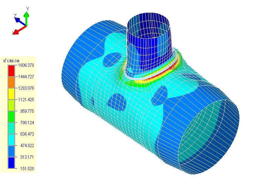 |
| Fig. 3.78. Total (membrane and bending) stresses on the outside surface, MPa |
FEM calculation of a shell with\without nozzle\support (attachment) is always performed, the another calculations are optional. Additionally can be made a calculation of stiffness (see [11] if calculation as per WRC was chosen) as well as hole reinforcement as per [14] (fig. 3.79).
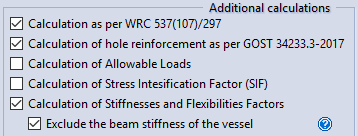 |
| Fig. 3.79. Specifying the type of calculation and type of shell |
When making calculations in conditions of corrosive hydrogen sulphide en-vironment, additional calculation results of total (membrane and bending) tensile stresses on the inside surface and membrane tensile stresses of branch connection are deduced. Estimation of the results obtained is made in accordance with [16].
Tables of allowable stresses on nozzle, both under influence of calculation pressure and without it, are displayed.
When activating stiffness calculation  ,
tables with nozzle stiffness and flexibility are displayed in the report
(in junction or on the edge of the nozzle) with appropriate directions of coordinate axis.
Unlike strength calculation,
branch connection strength calculation is made without regard to total allowances for elements thicknesses.
If local coordinate system was selected, a location for which the calculation of stiffness must be se-lected:
the edge of the nozzle or junction between nozzle and base shell.
,
tables with nozzle stiffness and flexibility are displayed in the report
(in junction or on the edge of the nozzle) with appropriate directions of coordinate axis.
Unlike strength calculation,
branch connection strength calculation is made without regard to total allowances for elements thicknesses.
If local coordinate system was selected, a location for which the calculation of stiffness must be se-lected:
the edge of the nozzle or junction between nozzle and base shell.
Activating strength calculation under low-cyclic loads  enables the calculation which based on [16] with consideration number of loading cycles,
loads range, etc. Where the stress amplitude is obtained by FEM.
enables the calculation which based on [16] with consideration number of loading cycles,
loads range, etc. Where the stress amplitude is obtained by FEM.
PASS/NOZZLE-FEM 3.5. Program Manual
Copyright © 2017-2026, PASS Team