

|
PASS/NOZZLE-FEM 3.5. Program Manual | |
In the course of deflected mode calculation of branch connection or conical element by finite element method (FEM), a linear 4-node shell-type element is used. For more detailed description of the element, estimation of its shape function, stiffness matrix, etc., see [22].
Deflected mode calculation by FEM makes it necessary to solve a linear equation system:
| $$ [C]\{\delta\} = \{F\}, $$ | (5.8) |
| here | $[C]$ | - stiffness matrix of design model, |
| $\{\delta\}$ | - nodal displacement vector, | |
| $\{F\}$ | - nodal force vector. |
Matrix [C] is symmetrical and strongly rared. To make strength calculation at specified loads, estimation of allowable loads and branch connection stiffness calculation, it is necessary to make from 8 to 14 calculations with the same matrix $[C]$ and different right members $\{F\}$.
For solution of the system of equations (5.8) the direct method based on $LDL^T$ expansion is used [23, 24]. This method assumes keeping of matrix non-zero elements in RAM of PC, that's why calculation time considerably depends on computer performance.
Design values of loads are applied in the centre of nozzle or shell head. The head represents itself a flat disk of high stiffness. Values and directions of forces and moments shall comply with charts shown in fig. 5.4.
 |
 |
| Fig. 5.4. Design loading systems for cylindrical shell (a) and dished head (b) | |
Estimation of the deflected mode results in junction zone is made automati-cally. At that local stresses are separated from the "peak" ones, which are placed in a very small zone of stress concentrators, rapidly decreasing and cause almost no influence in the course of the strength assessment of static calculations for structures fabricated of plastic materials. At the same time for local membrane and bending stresses a standard base on assessment of their limiting values is used (see section General).
For separation between "peak" stress zone and the "local" one there exists a technique developed by the well-known Paulin Research Group Company (creator of NozzlePRO, FEPipe, etc.). Finite elements directly abutted on the line of inter-section between branch pipe and shell ("welding" elements) possess tapered thick-ness, at estimation of which minimum weld dimensions are taken into account, as well as thicknesses of shell and branch pipe (fig. 5.5).
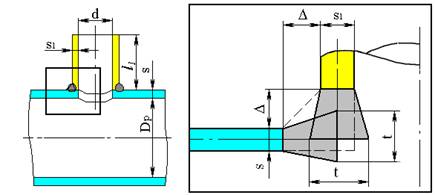 |
| Fig. 5.5. Dimensions of elements in junction zone |
At estimation of "welding" element thicknesses one should take into consideration a necessity of equality of weld, shell and nozzle stiffnesses in a welding zone.
On the one hand, thickness of elements being abutted on the nozzle (shell) shall be equated to the nozzle thickness $s_1$ (shell $s$), on the other hand, it shall be calculated by the following equations:
| $$ t = \max{ \left\{ \begin{array}{l} 1.5\frac{1.5ss_1 + 1.5\Delta{s} + 1.5\Delta{s_1} + \Delta^2}{2\Delta + 0.5s + 0.5s_1}, \\ \max{\{s,s_1\}} + 0.7\Delta, \\ \max{\{s,s_1\}} + 0.5\min{\{s,s_1\}} \end{array} \right\} }. $$ | (5.9) |
Maximum values of local stresses are calculated for elements directly abutted on the "welding" elements. Stresses for "welding" elements are not displayed.
The results achieved are considerably dependent on the quality of finiteelement meshing, especially in the zone of branch pipe junction into the shell, where a high stress gradient exists. With growing of element number (mesh level), circumscribing a junction zone, accuracy of calculation of the stress distribution increases.
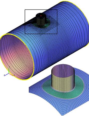
The program provides a possibility of making calculations with use of one of five mesh levels. First level corresponds to the mesh with the least number of elements, which allows making calculations with minimum time and RAM consumption. Fig. 5.6 shows an example of finite-element meshing for radial nozzle junction into the cylindrical shell with a pad, corresponding to the first mesh level.
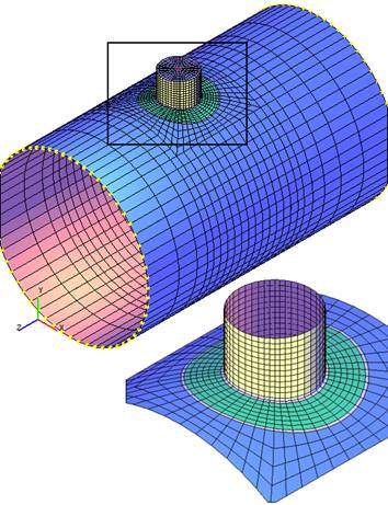 |
| Fig. 5.6. Finite-element branch connection model, corresponding to the first mesh level |
Use of 5th mesh level allows making calculation of maximum number of elements (fig. 5.7), but takes more time and RAM consumption.
 |
| Fig. 5.7. Finite-element branch connection model, corresponding to the fifth mesh level |
Besides, an accuracy of calculated stresses depends on the branch connec-tion type (availability of pad, tilting angle of a branch, etc.), difference between thicknesses of the shell and branch pipe, weld thickness, edge effect, etc.
To estimate influence of the above-mentioned factors on calculation accura-cy, a number of relative calculations for different branch connections were made.
Appraisal estimate of calculation results was carried out by relative accuracy for various types of loading.
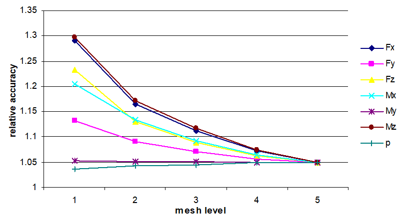
"Relative accuracy" means a ratio of calculated maximum stress values of 5th mesh level to the values of the current one. At that relative accuracy of the 5th mesh level shall be taken as 1.05.
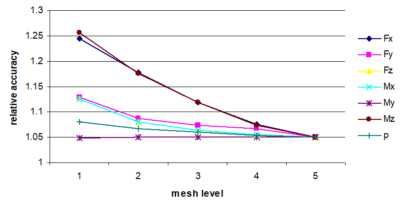
An influence caused by mesh levels of junction zone is shown in fig. 5.8 on the relative accuracy of calculated values of maximum stresses for various loads.
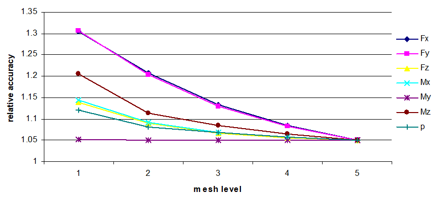 |
| Fig. 5.8. Relative accuracy of maximum stress values depending on the mesh level |
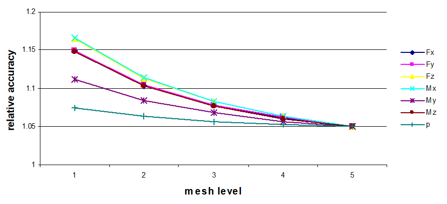
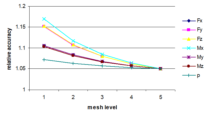
Fig. 5.9 shows influence of meshing on the obtained results of radial branch connection without pad.
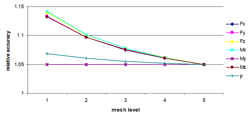 |
| Fig. 5.9. Relative accuracy of maximum stress values for radial branch connection into the cylindrical shell without pad |
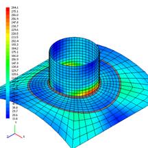
Fig. 5.10 shows an example of stress distribution of moment $M_z$, for the 1st & 5th mesh levels for branch connection with a pad.
 |
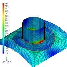 |
| Fig. 5.10. Equivalent membrane stresses from combined action of forces and pressure, MPa, for meshing by 1st (a) and 5th (b) levels of moment influence Mz=10000 Nm | |
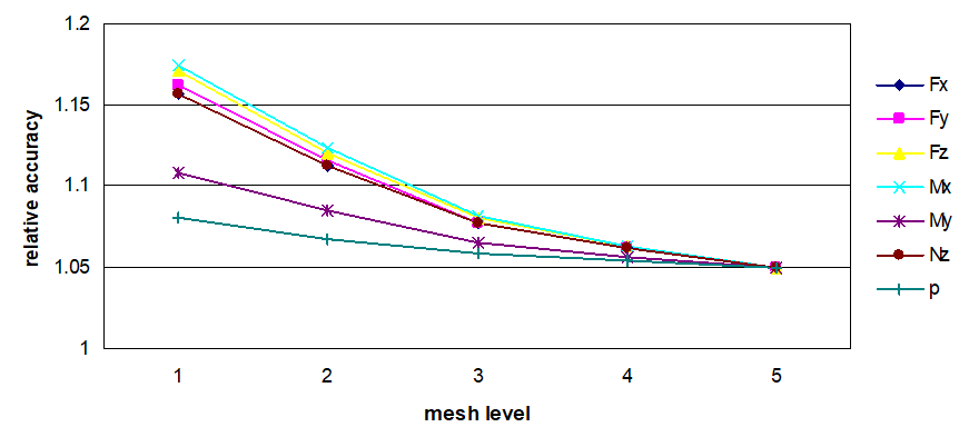
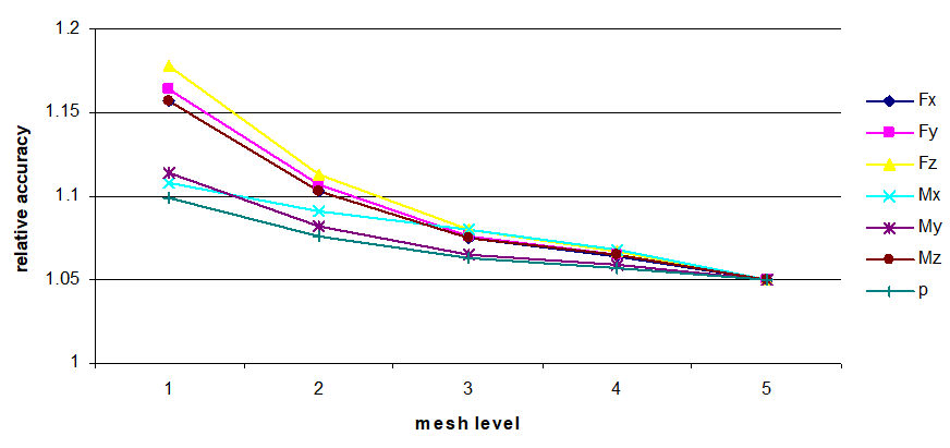
Influence of ratio between shell and branch pipe thicknesses on the calculation accuracy for different levels is shown in fig. 5.11 and 5.12.
 |
| Fig. 5.11. Relative accuracy of maximum stress values for radial branch connection into the cylindrical shell at $s/s_1=2$ |
 |
| Fig. 5.12. Relative accuracy of maximum stress values for radial branch connection into the cylindrical shell $s/s_1=0.5$ |
Fig. 5.13 shows an example of finite-element meshing for lateral branch connection into the elliptic head with a pad.
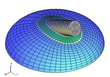 |
| Fig. 5.13. Finite-element model of lateral branch connection into the elliptic head with a pad |
Fig. 5.14 illustrates an influence caused by mesh levels on the relative accuracy of calculated values of maximum stresses for various loadings.
 |
| Fig. 5.14. Relative accuracy of maximum stress values for lateral branch connection into the elliptic head with a pad |
Fig. 5.15 illustrates an influence of meshing on the calculation results of the same lateral branch connection into the elliptic head, but without a pad.
 |
| Fig. 5.15. Relative accuracy of maximum stress values for lateral branch connection into the elliptic head without a pad |
As per calculations (fig. 5.16 and 5.17), a change in weld thickness causes virtually no influence on the result of the relative accuracy of the stresses obtained.
 |
| Fig. 5.16. Relative accuracy of maximum stress values for radial branch connection into the cylindrical shell with a weld thickness of $\Delta$=2mm |
 |
| Fig. 5.17. Relative accuracy of maximum stress values for radial branch connection into the cylindrical shell with a weld thickness of $\Delta$=20mm |
Generally speaking, an increase of mesh level means an increase of maximum stress values. At that mesh level causes maximum influence on the stresses by action of forces and moments, minimum — by action of pressure. Influence of mesh level increases on application of pad or when increase in thickness of the shell relative to the thickness of the branch pipe.
To reflect a quality of finite-element mesh regarding the estimation of the results obtained, so-called mesh coefficients $K_m$ is introduced. Their values are obtained on the basis of relative calculations made for various types of junctions. Maximum values of relative accuracy are selected for each mesh level.
Mesh coefficients increases safety factors and are used for calculation of allowable stresses for appropriate levels.
Accepted mesh coefficients, depending on their level, are given table 5.1. There is one personal assumption in 4th and 5th mesh levels for JB 4732-1995: $K_m$ = 1.0.
| Table 5.1. Mesh coefficients | |||||
| Mesh level | 1 | 2 | 3 | 4 | 5 |
| Mesh coefficient for nozzle junction, Km | 1.30 | 1.20 | 1.14 | 1.09 | 1.05 |
| Mesh coefficient for conical element, Km | 1.20 | 1.14 | 1.10 | 1.08 | 1.05 |
PASS/NOZZLE-FEM 3.5. Program Manual
Copyright © 2017-2026, PASS Team