

|
PASS/NOZZLE-FEM 3.5. Program Manual | |
Calculation results of nozzle's junctions may be considerably changed due to edge effect, arising when the nozzle is placed close to the edge of shell or head, where a fixation was made.
To exclude distortion of calculation results, distance from the shell (head, main pipe) edge to the outside surface of the nozzle (branch) shall not be less than half of its diameter $d/2$ (fig. 5.1).
 |
 |
| Fig. 5.1. The nozzle offset from shell end | |
For shell and main pipe:
| $$ \frac{d+2s_1}{2\cos(\gamma)} + \Delta + \frac{d}{2} \le L_n \le L - \left( \frac{d+2s_1}{2\cos(\gamma)} + \Delta + \frac{d}{2} \right); $$ | (5.1) |
- if pad is available:
| $$ \frac{d+2s_1}{2\cos(\gamma)} + L_2 + \Delta + \frac{d}{2} \le L_n \le L - \left( \frac{d+2s_1}{2\cos(\gamma)} + L_2 + \Delta + \frac{d}{2} \right). $$ | (5.2) |
For flat head:
| $$ |R_n| \le \frac{D+s}{2} - \left( \frac{d+2s_1}{2\cos(\gamma)} + \Delta + \frac{d}{4} \right); $$ | (5.3) |
- if pad is available:
| $$ |R_n| \le \frac{D+s}{2} - \left( \frac{d+2s_1}{2\cos(\gamma)} + L_2 + \Delta + \frac{d}{4} \right). $$ | (5.4) |
For hemispherical and elliptical heads:
| $$ |R_n| \le \frac{D}{2}. $$ | (5.5) |
Nozzle axis tilt angle in the cross-sectional plane of the shell:
| $$ |\psi| \le \arcsin\left(1- \frac{d+2(s_1+\Delta)}{D+2s} \right). $$ | (5.6) |
Nozzle (branch) axis tilt angle for shell, head and pipeline:
| $$ |\gamma| \le 60^{0}. $$ | (5.7) |
Besides the above limitations the program allows to carry out analysis of intersection line between branch pipe and shell. In case of plotting failure the program displays a message on invalid model layout.
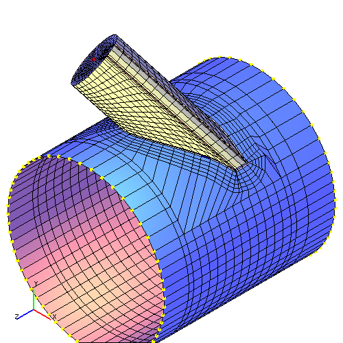
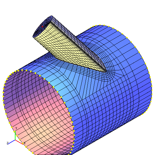
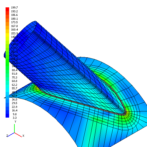
In spite of introduced limitations, it is necessary to preview a model meshing to finite elements in the course of analysis. For definite geometrical parameters of branch connection some finite elements can have inadmissible distortions (too acute angles, considerable ratios of conjugated parts lengths, etc.) or be confluent, which may cause incorrect results. An example of such meshing with calculation results is shown in fig. 5.2.
 |
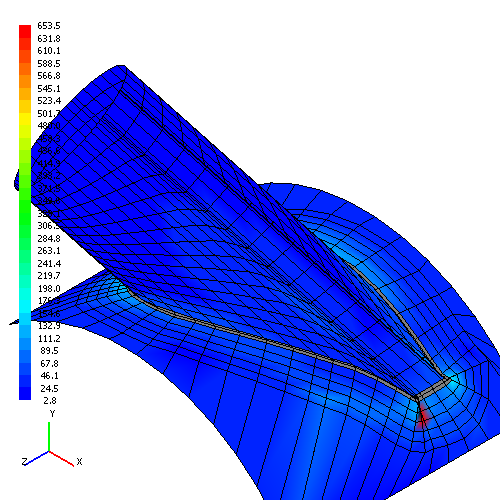 |
| Fig. 5.2. Finite element model of branch connections with confluent elements | |
For a solution of the problem it is often enough to make a slight change of branch connection parameters (reduction of diameter, tilt angle, etc.). Fig. 5.3 shows the same branch connection with the one in the fig. 5.2 with branch pipe diameter reduced from 600 to 570 mm.
 |
 |
| Fig. 5.3. Finite element model of branch connection with reduced diameter of branch pipe | |
PASS/NOZZLE-FEM 3.5. Program Manual
Copyright © 2017-2026, PASS Team