Additional data for parameters selection (goal-seek analysis)
In hydraulic and heat calculations of pipelines, quite often in practice the task of controlling certain flow parameters (pressure, temperature, flow rate, etc.) at various points of the pipeline by using various types of control valves, orifice plates, etc. is encountered. For these purposes, the Hydrosystem has a special service for selecting parameters of control devices to maintain specified values of target flow parameters at specified points of the pipeline, with the help of which it is possible to determine the parameters for setting control valves and other control devices in the pipeline.
This service is organized in a quite simple way: in addition to specifying the "usual" data for calculation (modeling a pipeline, setting the pumped fluid parameters, boundary conditions for the hydraulic calculation etc.), the user needs to specify what are the target parameters of the flow in the pipeline (which parameter and at what point in the pipeline needs to be controlled) and what are the control parameters (with the help of which regulation is done). For convenience, the tabs and fields with these parameters are highlighted in a separate color (blue) in the program windows. Please note that the number of control and target parameters must be the same, otherwise the calculation task will either not have a unique solution or will not have a solution at all.
The following target parameters are currently supported:
pressure after any piping component (pipe, valve, etc.);
flow temperature after any piping component (pipe, valve, etc.);
fluid flow rate in any branch of the pipeline.
To set target parameters, select the corresponding piping component (pipe, valve, etc.) at the end point of which it is necessary to control the flow pressure/temperature, or the pipeline branch on which it is necessary to control the flow rate, and open the "Parameters selection" tab in the Object Properties Window:
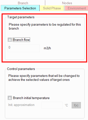
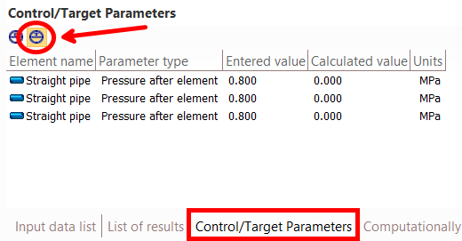
On this tab, you need to check the box next to the parameter you want to regulate and enter its required value. The list of entered target parameters can be seen in the Control/Target Parameters Window (to switch between control and target parameters, use the switch in the upper left part of this window):
The following control parameters are currently supported:
Kv flow coefficient of valves (any type);
opening degree of the gate valve rod;
butterfly valve closing angle;
orifice/pipe diameter of orifice;
initial temperature of the flow in the pipeline branch (available only for inlet pipeline branches).
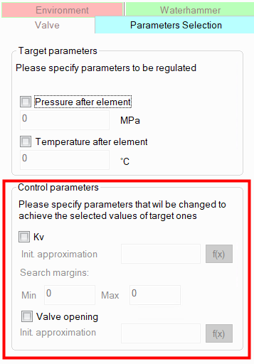
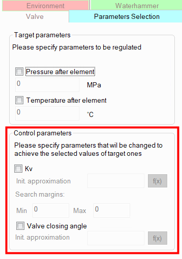
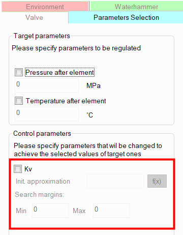
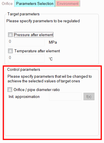
To set control parameters, select the corresponding valve, orifice or branch and open the "Parameters Selection" tab in the Object Properties Window:
Knife gate valve, gate valve or pinch valve |
|
Butterfly valve |
|
Other types of valves |
|
Orifice |
|
Branch * |
|
________________________________________
* - setting control parameters is available only for initial pipeline branches (product source branches). If control parameters for a branch are not displayed on the "Parameter selection" tab, this branch is not the initial one.
On this tab, you need to check the box next to the parameter that is the controlling one (the value of which you need to calculate) and enter its initial approximation (in the case of Kv, you also need to enter the search margins in which the program will search for a solution). Usually, the default initial approximations and search boundaries allow to find a solution in most cases. However, in some rare cases it may be necessary to adjust the initial approximation and/or search boundaries (for example, if the solution lies in the area of very small or, conversely, very large values of the control parameter), if the calculation with the default initial approximation and search boundaries does not converge or takes a long time.
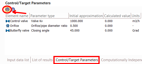
The list of entered control parameters can be seen in the Control/Target Parameters Window (to switch between control and target parameters, use the switch in the upper left part of this window):
Target and control parameters can be set both on the same and on completely different pipeline elements. This does not matter for the calculation.
Calculation with selection of parameters and its settings
Once all target and control parameters have been set, you simply need to run the isothermal flow calculation or heat and hydraulic analysis of the pipeline. You can monitor the progress of the calculation with parameter selection in the status bar (at the bottom of the program window), which displays the number of the current calculation iteration (on the left) and the overall progress of the calculation (on the right), as well as in the Control/Target Parameters Window, which dynamically displays the current values of the control parameters. If necessary, parameters selection can be interrupted by clicking the corresponding button in the status bar.
After the calculation is completed, the Control/Target Parameters Window will display the resulting values of the control and target parameters (use the switch at the top of this window to switch between control and target parameters). The results can also be viewed in the isothermal/heat and hydraulic calculation results list window. If it is impossible to select the parameters, a corresponding message will be displayed in the calculation log window.
The settings for the calculation with parameter selection - the maximum number of iterations and the relative calculation error - can be edited (this can be useful, for example, if you need to speed up the calculation). To edit them, select the pipeline in the project tree and go to the "Parameters selection" tab of the Object Properties window :
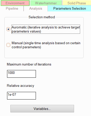
For "manual" selection of parameters and variables, see below.
Please note that the formulation of the parameter selection calculation task should be such that it is physically feasible in practice. For example, if the target parameter is the fluid temperature at some point in the pipeline, and the control parameter is the Kv coefficient of some valve, it is important to understand that the fluid temperature weakly responds to changes in the valve capacity (only indirectly through the flow rate in the branch, and not in all cases). Therefore, such a calculation task will most likely not have a solution. Or, for example, if it is necessary to adjust the flow rate in a branch, the boundary conditions for the hydraulic calculation should be set in such a way that the flow rate in this branch is an unknown value (if the flow rate is set, its value is known and will not depend on any other parameters of the pipeline elements, so it will not be possible to adjust it). For clarity, below are examples of the most common in practice options for parameters selection and regulators sizing calculation tasks and.
Downstream pressure control device
To calculate the parameters of such a control device it is necessary:
model it as valve (no matter what type);
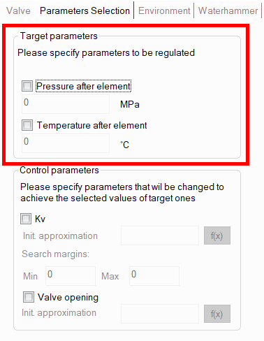
open the "Parameters selection" tab of the Object Properties Window for it and check the Kv coefficient as a control parameter;
there, on the “Parameter selection” tab, check the “Pressure after element” box as the target parameter and enter the required pressure value (which the regulator must maintain “after itself”);
perform pipeline calculation.
Please note that if the boundary conditions for hydraulic calculation are set in such a way that the pressure is known at the end points of the pipeline, and the flow rates are set at the sources, then the calculation task of selecting the parameters of the downstream pressure control device will most likely not have a solution. It will not be possible to select the parameters of the regulator in this case, since the value of the pressure after the regulator will be determined to a greater extent by the pressure at the end point of the pipeline than by the settings of the regulator itself (that is, for any parameters of the regulator, the pressure after it will be approximately the same). Therefore, when selecting the parameters of the downstream pressure regulators, a different set of boundary conditions for hydraulic calculation should be used.
Upstream pressure control device
To calculate the parameters of such a control device it is necessary:
model it as valve (no matter what type);
open the "Parameters selection" tab of the Object Properties Window for it and check the Kv coefficient as a control parameter;
select the piping component preceding this regulator, open the "Parameters selection" tab of the Object Properties Window for it, check the “Pressure after element” box as the target parameter and enter the required pressure value (which the regulator must maintain "before itself");
perform pipeline calculation.
Please note that if the boundary conditions for hydraulic calculation are set in such a way that the pressure is known at the initial points of the pipeline, and the flow rates are set at the consumers, then the calculation task of selecting the parameters of the upstream pressure control device will most likely not have a solution. It will not be possible to select the parameters of the regulator in this case, since the value of the pressure before the regulator will be determined to a greater extent by the pressure at the initial point of the pipeline than by the settings of the regulator itself (that is, for any parameters of the regulator, the pressure before it will be approximately the same). Therefore, when selecting the parameters of the upstream pressure regulators, a different set of boundary conditions of hydraulic calculation should be used.
Control pressure at any point in the pipeline
To calculate the parameters of such a control device it is necessary:
model it as valve (no matter what type);
open the "Parameters selection" tab of the Object Properties Window for it and check the Kv coefficient as a control parameter;
select the piping component (pipe, bend, etc.) at the end point of which the pressure needs to be adjusted, open the "Parameters selection" tab of the Object Properties Window for it, check the “Pressure after element” box as the target parameter and enter the required pressure value;
perform pipeline calculation.
In essence, this type of regulator is a more generalized case of a "upstream" or "downstream" pressure control devices (depending on where the regulator is located relative to the point in the pipeline where it regulates the pressure). Therefore, when setting the boundary conditions for hydraulic calculations, the above recommendations for the corresponding type of regulator should be taken into account.
To calculate the parameters of such a control device it is necessary:
model it as valve (no matter what type);
open the "Parameters selection" tab of the Object Properties Window for it and check the Kv coefficient as a control parameter;
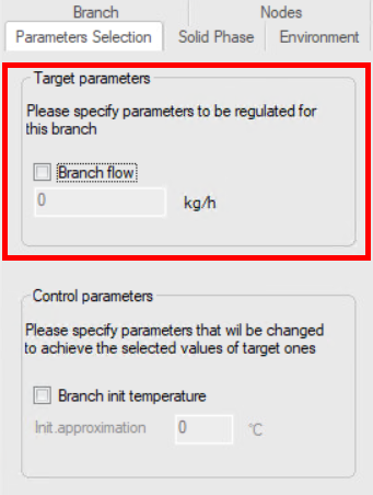
select the pipeline branch in the project tree in which the fluid flow rate needs to be controlled, open the "Parameters selection" tab of the Object Properties Window for it, check the "Branch flow" box as the target parameter and enter the required flow rate value;
perform pipeline calculation.
Please note that the boundary conditions for the hydraulic calculation in this case must be set in such a way that the pressure is set at least in one point of the pipeline before and at least in one point after the regulator (usually in this case the pressures are set in all source and consumer nodes).
Note: In addition to using the "Parameters selection" service, you can also calculate the flow control valve settings using the Control valve component.
In practice, there may be situations when it is necessary to ensure a certain value of the flow temperature at some point in the pipeline (usually at the end point) and for this it is necessary to determine at what temperature the fluid must be supplied to the pipeline (at its starting point). Moreover, such a task can be encountered both for pipelines with one source and for pipelines with several sources (when flows with different temperatures are mixed). To solve such a task, it is necessary:
select the piping component (pipe, bend, etc.) at the end point of which it is necessary to control the temperature, open the "Parameters selection" tab of the Object Properties window for it, check the "Temperature after element" box as the target parameter and enter the required temperature value;
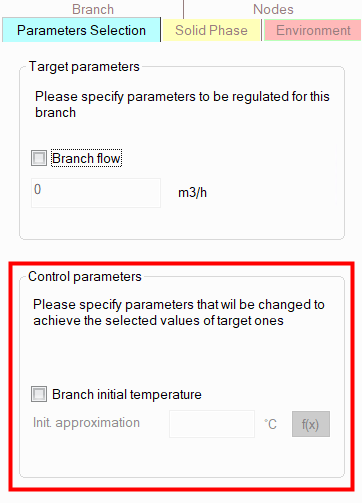
select the inlet branch of the pipeline in the project tree, for the initial point of which it is necessary to determine the required initial flow temperature, open the "Parameters selection" tab of the Object Properties Window for it, check the "Branch init temperature" box as a control parameter and enter the initial approximation of the temperature value (see below);
perform pipeline calculations.
When choosing the initial approximation for temperature, it is necessary to show a little "engineering intuition" and set a temperature value close to the expected one. The search for a temperature solution is carried out in the range of plus/minus 20 degrees relative to the specified value, so if you set a value that is very "far from the truth", the parameters selection may end unsuccessfully. However, after each calculation with parameters selection, the value of the initial approximation is replaced by the final value of the control parameter obtained in this calculation (that is, the initial approximation of plus or minus 20 degrees, depending on which direction the search was in). So, by sequentially performing several such calculations in a row, you can "step closer" to the required temperature values and eventually "get" to the solution.
Usually, when selecting the required initial flow temperature, the fluid flow rate in the pipeline is a known value; however, it is also permissible to specify known pressures at the initial and final points of the pipeline as boundary conditions for the hydraulic calculation.
Calculation of a 'mixer' for temperature control after mixing the 'cold' and 'hot' flows
In practice, it is not often, but nevertheless, such a task can also be encountered when two flows with different temperatures are mixed, and it is necessary to determine the ratio of the flow rates of the "hot" and "cold" flows, at which the required temperature of the fluid after mixing will be obtained. To solve such a task, it is necessary:
select a piping component (pipe, bend, etc.) after mixing the flows, at the end point of which it is necessary to obtain the required temperature after mixing, open the "Parameters selection" tab of the Object Properties window for it, check the "Temperature after element" box as the target parameter and enter the required temperature value;
add any type of valve to one of the source branches (with a "hot" or "cold" flow - it doesn't matter), open the "Parameters selection" tab of the Object Properties Window for it and check the Kv coefficient as a control parameter;
perform pipeline calculation.
That is, the regulation of the flow ratio is carried out indirectly through the coefficient of the flow capacity of the control valve (on which, in turn, this flow depends). The boundary conditions for the hydraulic calculation must be set in such a way that the fluid flow in the branch with this valve is a variable (unknown) value, that is, the pressure must be set at the beginning of this branch (or upstream before it). Moreover, for another source branch in this case, both the known pressure at the starting point and the known flowrate can be set as a boundary condition.
An extremely rare case in practice, but nevertheless - you may encounter such a task when you need to determine how fast (at what flow rate) the flow must be pumped in a pipeline so that it does not cool down/warm up too much along the flow. To solve such a task, you need to:
select a piping component (pipe, bend, etc.) at the end point of which you need to obtain the required flow temperature, open the "Parameters selection" tab of the Object Properties Window for it, check the "Temperature after element" box as the target parameter and enter the required temperature value;
add any type of valve to the pipeline, open the "Parameters selection" tab of the Object Properties Window for it and check the Kv coefficient as a control parameter;
perform pipeline calculation.
That is, the flow rate regulation, as in the previous case, is carried out indirectly through the coefficient of the flow capacity of the control valve (on which, in turn, this flow rate and therefore a temperature depend). The boundary conditions for the hydraulic calculation must be set in such a way that the fluid flow rate in the branch with the given valve is a variable (unknown) value.
Calculation of the orifice diameter to control pressure or flowrate
Selecting the required diameter of the throttle orifice plates to regulate the required pressure/flow value is essentially similar to the calculation of the flow control device and pressure regulator at any point in the pipeline discussed above. To select the diameter of the orifice, it is necessary:
add an orifice open the "Parameters selection" tab of the Object Properties window for it and check the orifice/pipe diameter ratio as a control parameter;
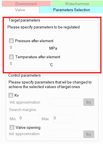
select either the branch in which the flow rate needs to be adjusted, or the piping component (pipe, bend, etc.) at the end point of which the pressure needs to be controlled, then open the "Parameters selection" tab of the Object Properties window for it, check the "Pressure after element"/"Branch flow" box as the target parameter and enter the required pressure/flow rate value;
perform pipeline calculation.
For recommendations on boundary conditions for hydraulic calculations, see the relevant sections above on calculations of flow control device and pressure regulator at any point in the pipeline.
The selection of the required position of the gate valve rod and the flap angle of the butterfly valve to regulate the required pressure/flow value is essentially similar to the calculation of the flow control device and pressure regulator at any point in the pipeline discussed above. To perform such a calculation, it is necessary:
add the appropriate type of valve (gate valve or butterfly valve), open the "Parameters selection" tab of the Object Properties window for it and check the "Valve opening" or the "Valve closing angle" (depending on the selected type of valve) as a control parameter;
select either the branch in which the flow rate needs to be adjusted, or the piping component (pipe, bend, etc.) at the end point of which the pressure needs to be controlled, then open the "Parameters selection" tab of the Object Properties window for it, check the "Pressure after element"/"Branch flow" box as the target parameter and enter the required pressure/flow rate value;
perform pipeline calculation.
For recommendations on boundary conditions for hydraulic calculations, see the relevant sections above on calculations of flow control device and pressure regulator at any point in the pipeline.
In practice, there are calculation tasks when it is necessary to determine what thickness of thermal insulation is required so that the temperature of the fluid does not fall/rise more than by a certain permissible value. Unfortunately, Hydrosystem is currently unable to solve such a calculation tasks automatically. If such calculations are of practical interest to you, please inform the program developers by e-mail hydro@passuite.com.
Calculation of pipeline roughness value for 'calibration' of the pipeline calculation model
In practice, especially for pipeline systems already in operation, there are calculation tasks of calibration of the calculation model of the pipeline. Most often, it comes down to determining the exact value of the roughness of the pipe walls (or possibly some other characteristics of the pipeline), at which the calculation model will exactly describe the behavior of a real pipeline, for which there are experimental data on the values of pressure at various points of the pipeline, flow rates, fluid velocities, etc. Unfortunately, Hydrosystem is currently unable to solve such a calculation tasks automatically. If such calculations are of practical interest to you, please inform the program developers by e-mail hydro@passuite.com.
Calculation of the diameter value to provide the required multi-phase flow pattern
For pipelines with a two phase gas-liquid flow, one of the main objectives of hydraulic calculation is to ensure that the flow in a pipeline doesn't operate in intermittent (plug, slug) flow pattern. Since the two-phase flow pattern directly depends on the pipe diameter, in practice this task comes down to selecting such a diameter value at which any flow pattern except intermittent flow will form in the pipeline. Unfortunately, Hydrosystem is currently unable to solve such a calculation tasks automatically. If such calculations are of practical interest to you, please inform the program developers by e-mail hydro@passuite.com.
Also in the parameters selection settings you can switch between the “traditional” automatic selection of parameters and the so-called “manual”, in which, in fact, the selection of parameters is not carried out, but a one-time calculation of the pipeline is performed with the values of the control parameters that are specified for the piping components on the “Parameters Selection” tab. This type of calculation is useful because it allows to set the values of the control parameters by using the variables that can be set by clicking the corresponding button below:
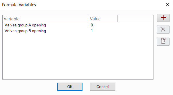
The variables added here (they can be added, removed and edited using the corresponding buttons on the right side of the window) can then be used in control parameters:
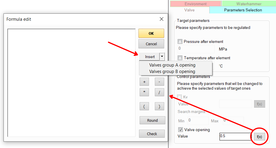
Thus, if you need to set/change any parameter for several elements of the pipeline at once (for example, valve closing angle, if you need to open/close several valves at the same time), instead of setting its value for each element separately, you can add a variable and set this variable (or some arithmetic expression involving it) in the formula for the control parameter. When setting/changing the value of this variable, it will immediately be assigned to all control parameters for which this variable is used.